1OM-1050-002.pdf - 第87页
2.4.7 P .E.C. Recognition Section Fig. 1A25 The P .E.C. recognition camera is used to detect the fiducial marks on a P .C.B. and the amount of the positional deviation from the fiducial mark coordinate data is calculated…
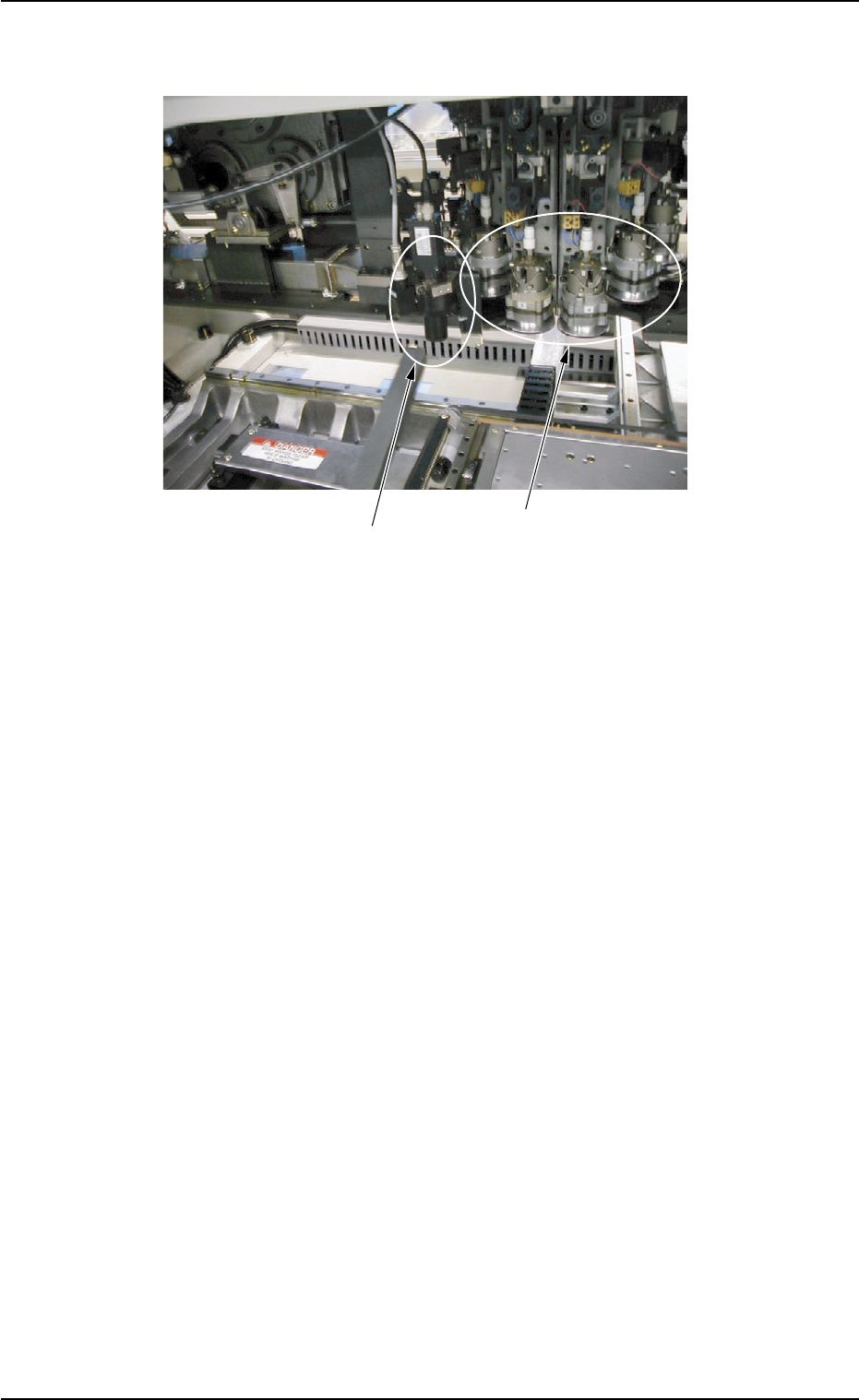
2.4.6 Component Recognition Section
Fig. 1A24
The machine is provided with a mechanism that inspects (recognizes)
the components picked up by vacuum nozzles, using two component
recognition cameras and three light sources.
The following three operations are performed in the component
recognition system.
•
Component Detection
•
Component Inspection based on Component Library Data
•
Measurement of Positional and Angular Deviations
Component Recognition Camera
2.4 Main Units
0207-003 1-27 AFO01EOPP
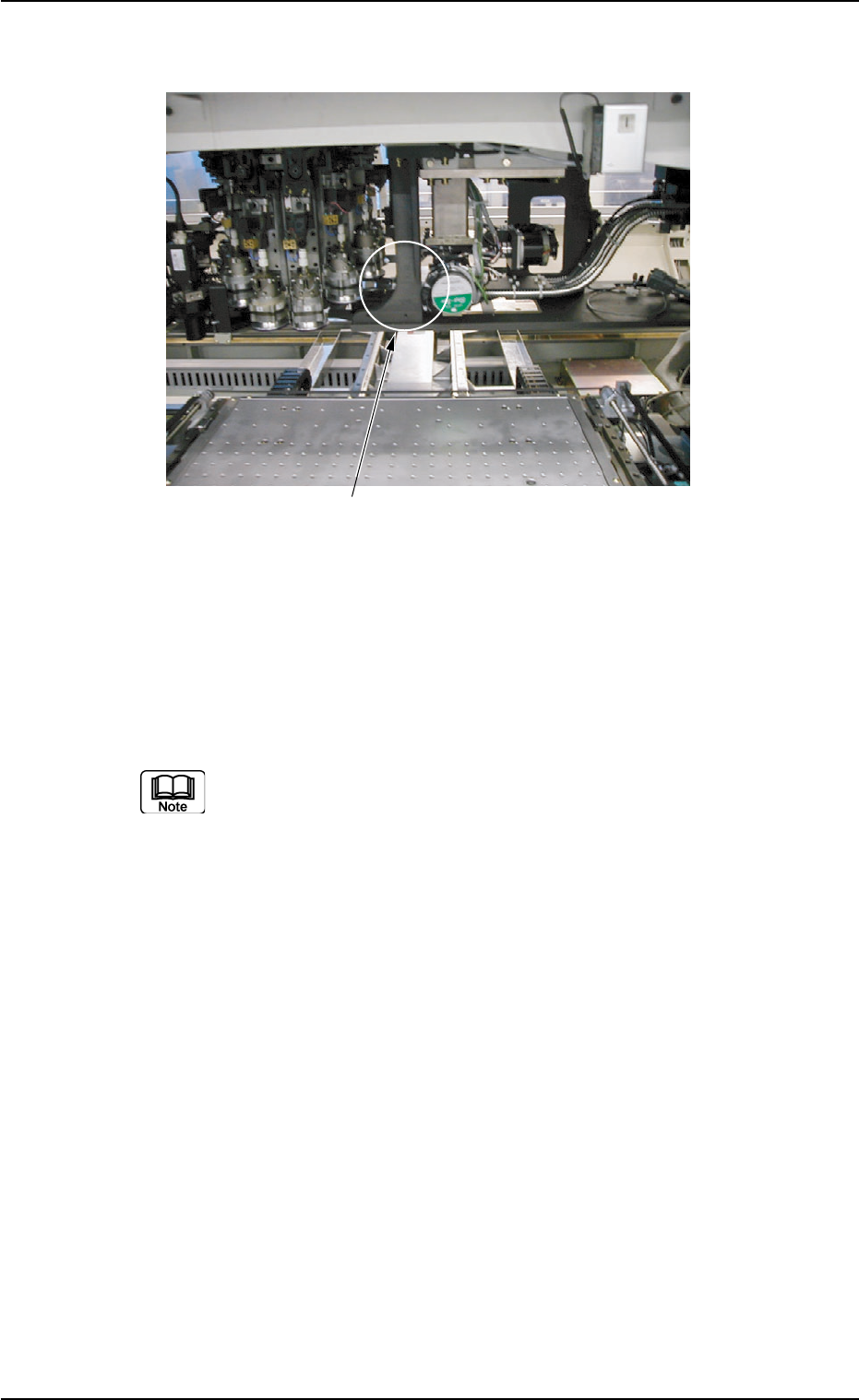
2.4.7 P.E.C. Recognition Section
Fig. 1A25
The P.E.C. recognition camera is used to detect the fiducial marks on a
P.C.B. and the amount of the positional deviation from the fiducial mark
coordinate data is calculated to automatically correct the position of a
placed component.
P.E.C. Recognition Camera
Rotary Turret
0102-002 1-28 AFO01EOPP
2.4 Main Units
0102-002 1-29 AFO01EOPP
3. Surface Mounting Mechanism
The following briefly describes how components are mounted on P.C.B.’s.
(a) The explanation is based on the P.C.B. flow direction "From
Left to Right (L R)".
(b) Refer to "1. Scope of Actions" in "Section 2" of "Volume 2:
Operation (Supervisor)" for details.
3.1 P.C.B. Transfer and Positioning
P.C.B. Transfer (from the input machine)
The P.C.B. transferred from the input machine is carried to the P.C.B.
transfer section by the L conveyor and stops there.
Fig. 1A40
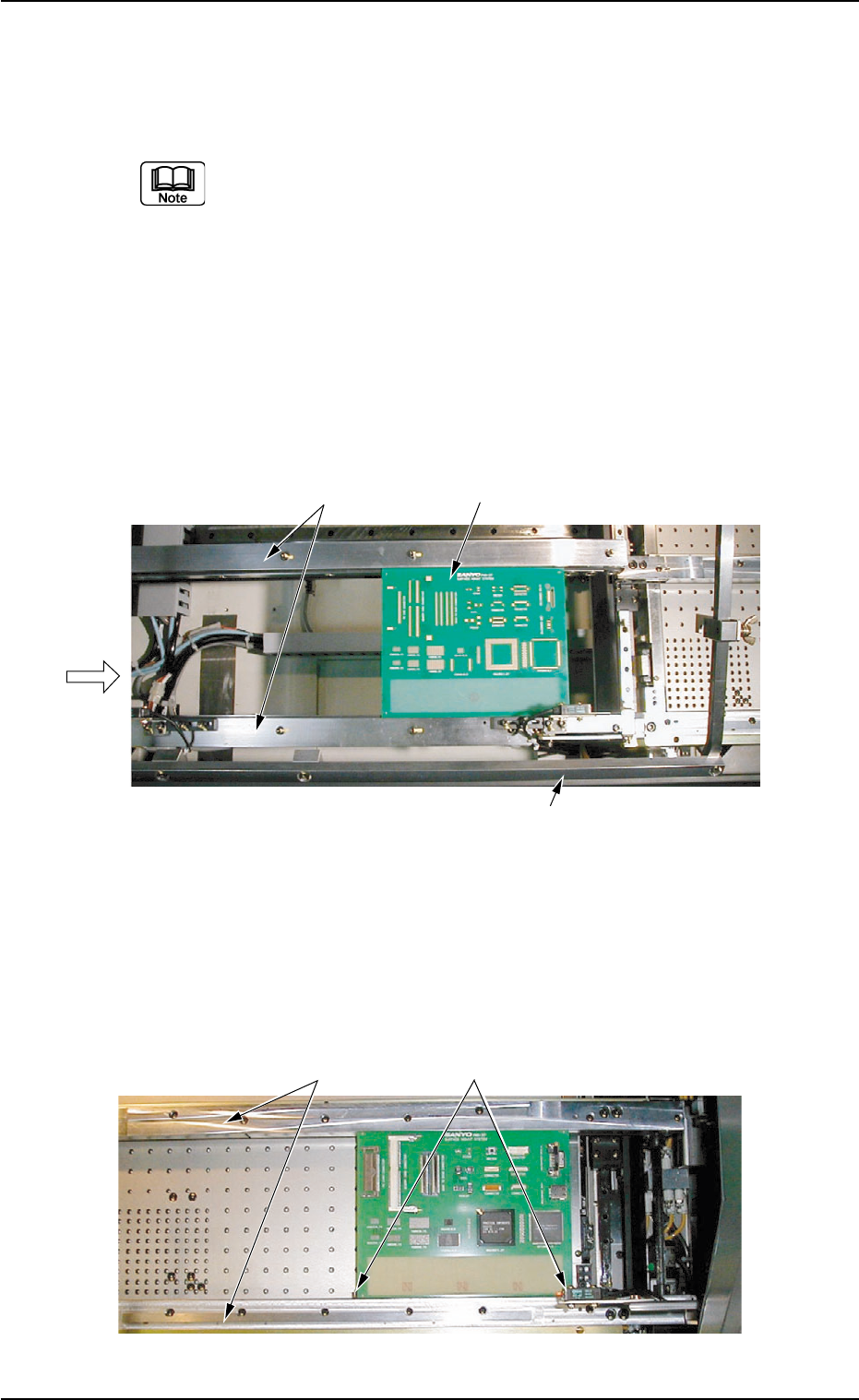
P.C.B. Positioning
The P.C.B. transferred from the P.C.B. transfer section to the X/Y
table is secured in place by the chutes, the P.C.B. pilot pins, etc., on
the table.
Fig. 1A41 X/Y Table Section
3. Surface Mounting Mechanism
L Conveyors
P.C.B.
P.C.B. Transfer Section
Input Machine
Chutes
P.C.B. Pilot Pins