1OM-1050-002.pdf - 第129页
(4) Press the [OPN. MODE] button on the submenu bar to open the "OPN. MODE" submenu window . After that, press the [P ASS] but- ton entitled "RUN MODE" in the "Run Mode" tab sheet. Fig. 1C28…
2. "PASS" Mode
When the machine is set in the "PASS" mode, it just carries the P.C.B.
(input conveyor P.C.B. positioning section output conveyor) to the
output conveyor without placing any components on the P.C.B.
When the machine must transfer P.C.B.’s to the output machine with-
out placing any components, follow the steps below.
2.1 Start of "PASS" Operation
(1) Ensure the safety around the front safety door and the feeder car-
riage sections.
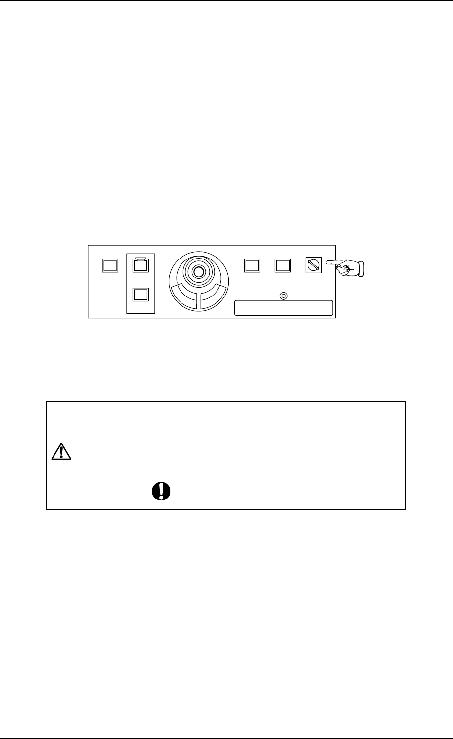
(2) Set the [OPERATION] switch on the front operation panel to "RUN".
Be sure to remove the key from the machine.
Fig. 1C27
(3) Check the surroundings of the machine and confirm safety before
starting the "PASS" operation.
CAUTION
Check carefully that there is no person around the
moving mechanisms of the machine. (Especially, the
other side of machine operation).
Make sure that no objects (tools, parts, etc.) remain
within the moving mechanisms of the machine.
0307-004 3-23
AFO01EOPP
2. "PASS" Mode
219'410
5612
56#46 '0#$.'
4705'672
12'4#6+10
.1%-
20.%*#0)'
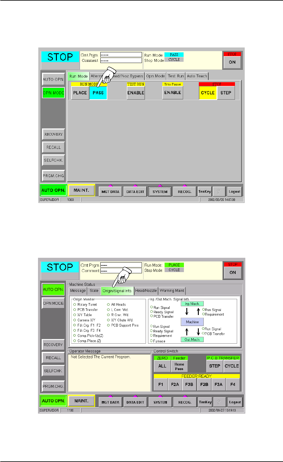
(4) Press the [OPN. MODE] button on the submenu bar to open the
"OPN. MODE" submenu window. After that, press the [PASS] but-
ton entitled "RUN MODE" in the "Run Mode" tab sheet.
Fig. 1C28
(5) Perform the zeroing operation in the "Origin/Signal Info." tab sheet
of the "AUTO OPN." submenu window.
Fig. 1C29
0210-005 3-24
AFO01EOPP
2.1 Start of "PASS" Operation
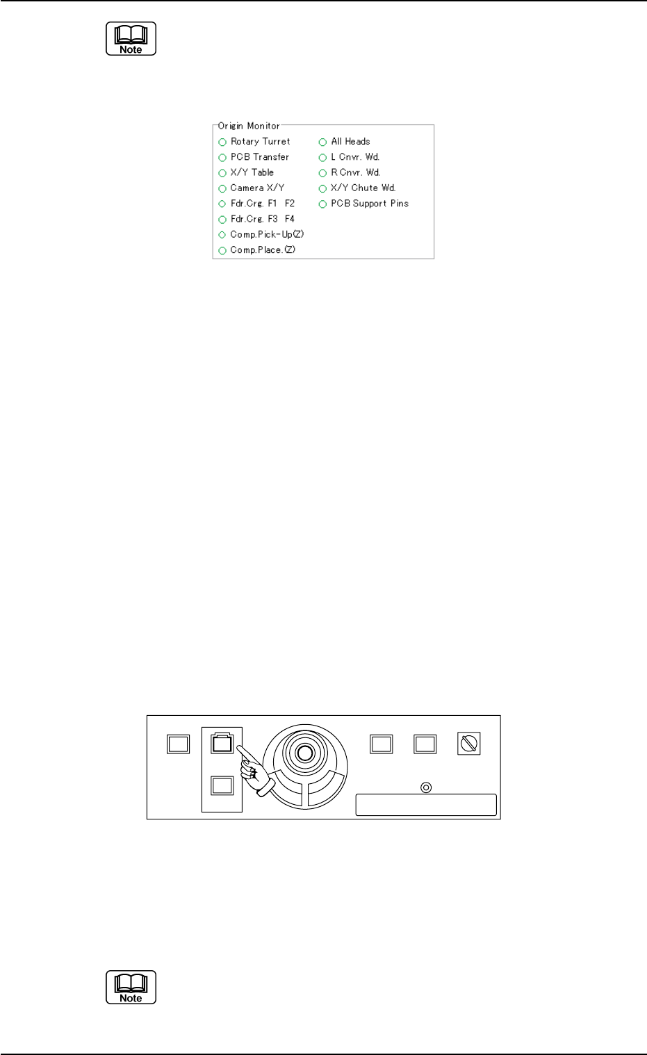
When the origin marks "
•
" are not displayed for all devices ex-
cept "L Cnvr. Wd.", "R Cnvr. Wd.", "X/Y Chute Wd.", and "PCB
Support Pins" in the "Origin Monitor" group box of the "Origin/
Signal Info." tab sheet, the pass operation cannot be started.
Fig. 1C30
When the origin mark "
•
" does not appear before any device other than
"L Cnvr. Wd.", "R Cnvr. Wd.", "X/Y Chute Wd.", and "PCB Support Pins",
follow the steps below to perform the zeroing operation.
Operation Procedure
1. Confirm that the machine is set in the "STOP" mode.
2. Confirm that the front safety door, the feeder work area safety doors,
and the feeder carriage cover are closed.
3. When the [ENABLE] button on the operation panel is pressed in 2
seconds after the [ALL] button (entitled "ZERO"), all devices except
"L Cnvr. Wd.", "R Cnvr. Wd.", "X/Y Chute Wd.", and "PCB Support
Pins" are zeroed.
(6) When the [START] button on the front operation panel is pressed
while it is flickering, the pass operation starts.
When the input machine is not set ready, this machine stays in the
"WAIT" mode.
Fig. 1C31
When the "PASS" operation starts, all origin marks disappear and the
LED (green) of the [START] button on the front operation panel and the
green lamp of the light tower illuminate.
(a) The "PASS" operation cannot be started unless the "AUTO
OPN." window is active.
(b) When a P.C.B. already exists in the P.C.B. positioning sec-
tion, it is discharged.
0307-005 3-25
AFO01EOPP
2.1 Start of "PASS" Operation
219'410
5612
56#46 '0#$.'
4705'672
12'4#6+10
.1%-
20.%*#0)'