1OM-1050-002.pdf - 第84页
2.4.4 X/Y T able Section Fig. 1A21 The X/Y table section is provided with a mechanism that holds a P .C.B. (sent from the conveyor on the input side) firmly on the X/Y table. The firmly-held P .C.B. moves and stops under…
2.4.3 P.C.B. Transfer Section
Fig. 1A20
The P.C.B. transfer section is equipped with a feed claw that pushes
and transfers the P.C.B. (the P.C.B. received from the input machine by
the L conveyor when the flow direction is "L R") onto the X/Y table.
CAUTION
It is very dangerous for a person or a thing to come in
contact with the feed claw.
Special care is required during working with the front
safety door being open.
0110-003 1-24 AFO01EOPP
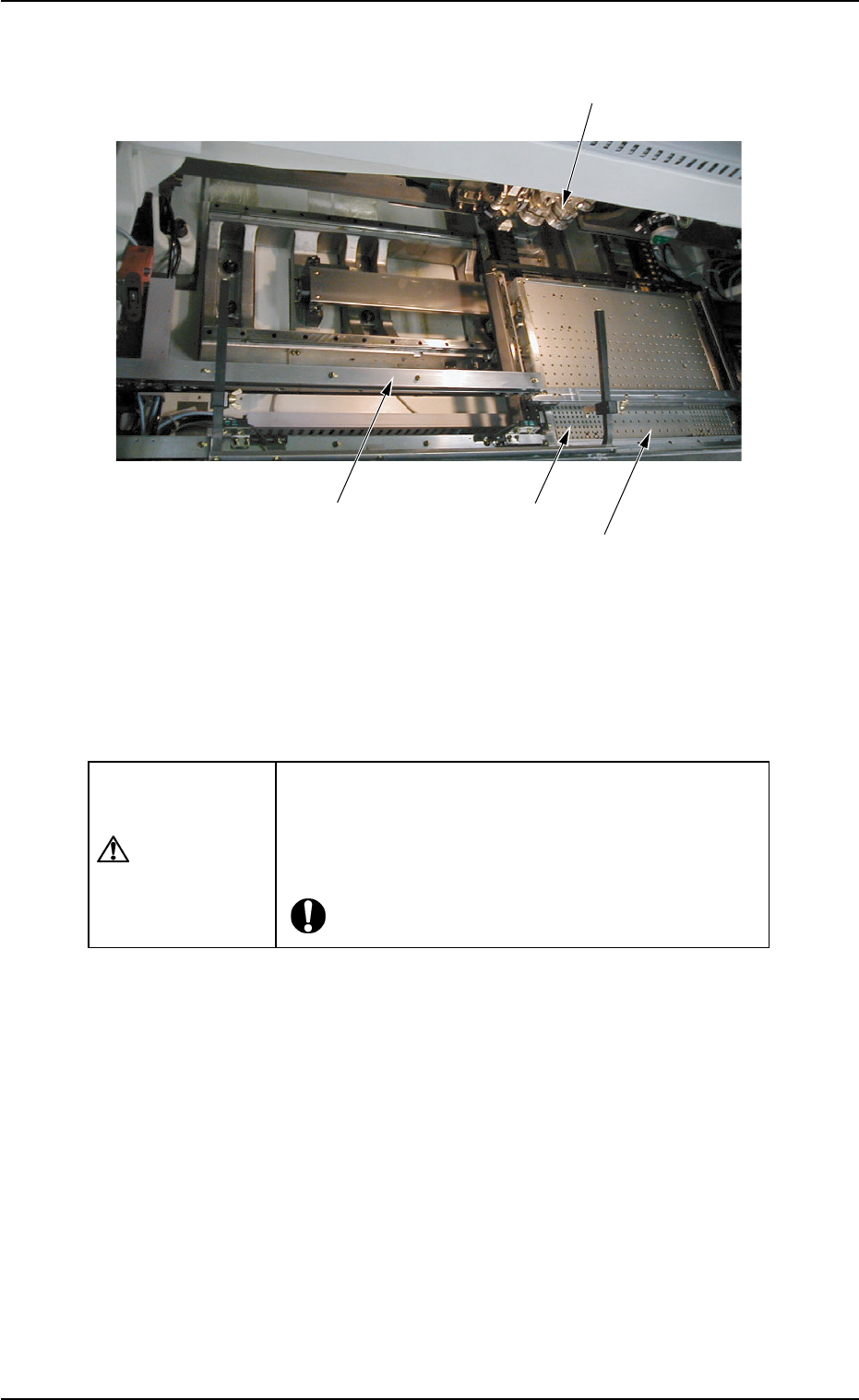
2.4 Main Units
Rotary Turret
L Conveyor
X/Y Table
P.C.B. Transfer Claw
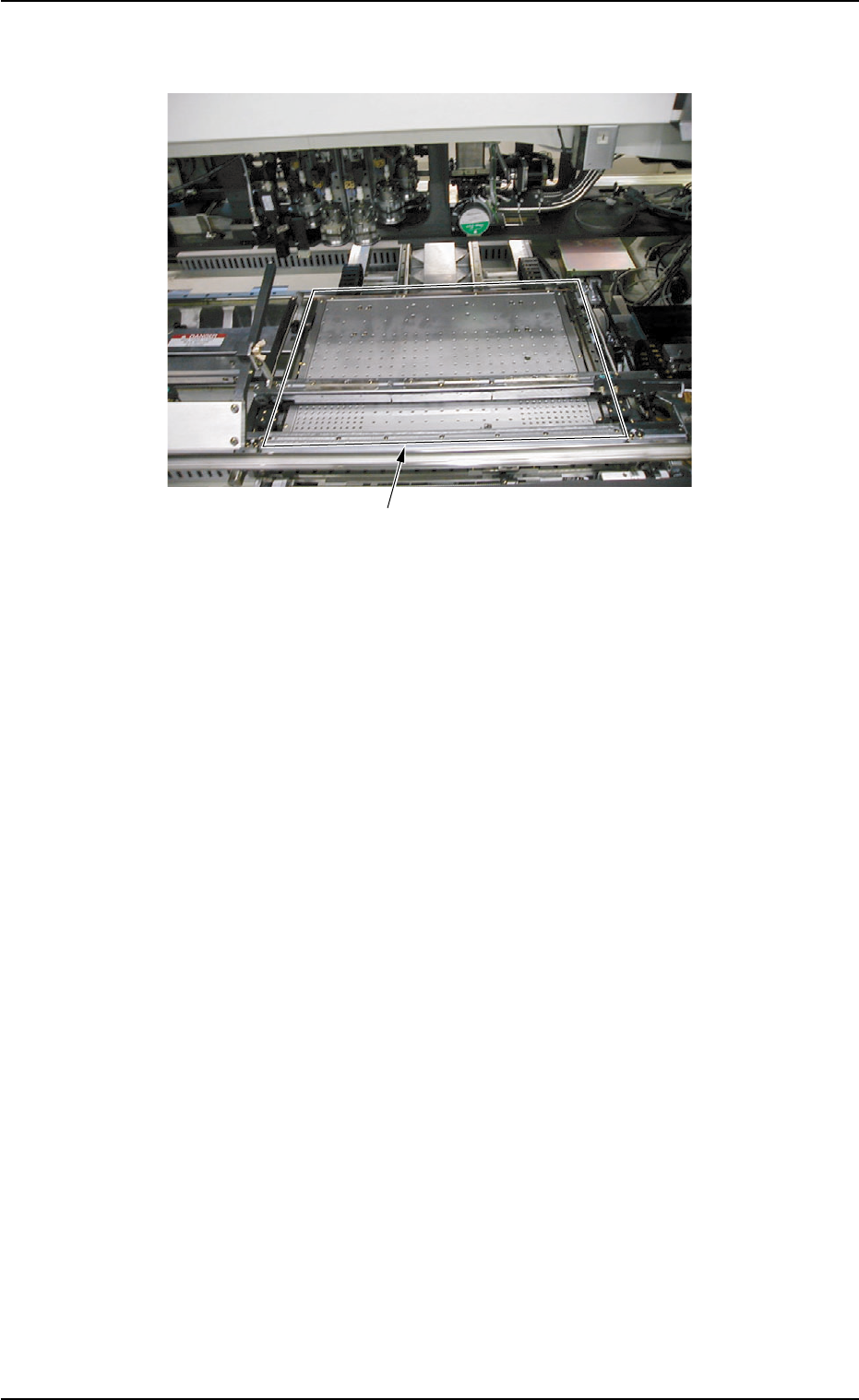
2.4.4 X/Y Table Section
Fig. 1A21
The X/Y table section is provided with a mechanism that holds a P.C.B.
(sent from the conveyor on the input side) firmly on the X/Y table.
The firmly-held P.C.B. moves and stops under the placement heads
together with the X/Y table according to the pattern program data. Com-
ponents are placed on the P.C.B. there.
It is required to adjust the positioning pin, the positioning lever, and the
movable chute to firmly hold the P.C.B. (P.C.B. positioning).
X/Y Table
2.4 Main Units
0102-002 1-25 AFO01EOPP
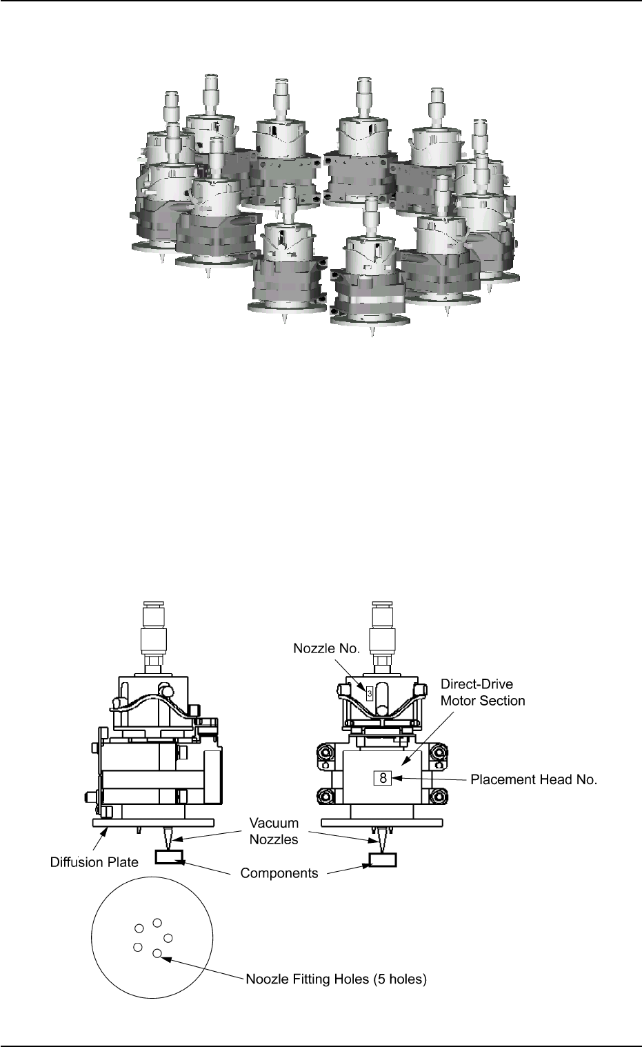
2.4.5 Placement Head Section
Fig. 1A22
The machine is provided with a rotary turret that has several heads.
Each head is rotated by a direct-drive motor and several vacuum nozzles
can be attached to one head. The attached vacuum nozzles are used to
pick up components and place them on a P.C.B.
The turret has 12 placement heads.
Each head has 5 fitting holes for nozzles. Up to 5 types of vacuum
nozzles can be attached to each head.
Fig. 1A23
0110-003 1-26 AFO01EOPP
2.4 Main Units