1OM-1050-002.pdf - 第66页
2.3.3 Front Operation Panel Fig. 1A1 1 Arranged on the operation panel are switches and buttons required to operate the machine. The machine is provided with front and rear operation panels and can be operated from eithe…
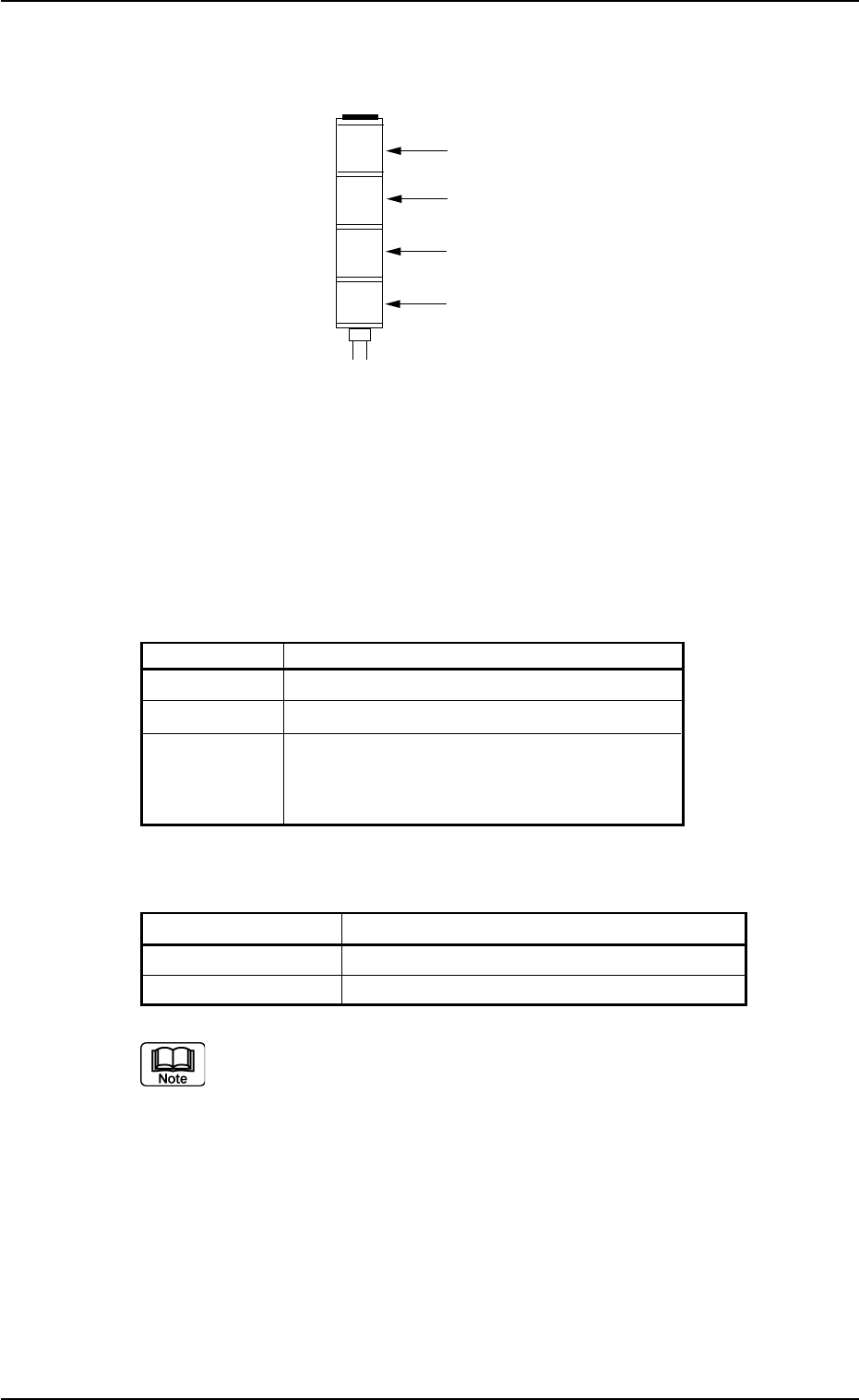
2.3.2 Light Tower
Fig. 1A10
The light tower indicates the condition of the machine with the lamps
and buzzer sounds.
Lamp Colors
The machine is factory-adjusted upon shipment.
Table 1A2
Lamp Colors Machine Condition
Red Error (Machine Stop)
Yellow Component Shortage (Warning)
Green Automatic Operation
Note: When the machine is in the standby
mode, this lamp flashes.
Buzzer
Table 1A2-1
Buzzer Machine Condition
Continuous Sound Emergency Stop
Intermittent Sound Error Occurrence
The condition of the machine corresponding to the parameters
specified for each lamp color and buzzer sound can be changed
in the "Configuration Setup" tab sheet.
Refer to "3.4 "Configuration Setup" Tab" in "Section 5" of "Vol. 3
Programming and Machine Data" for details.
2.3 Operational Measures
0207-003 1-11 AFO01EOPP
Red
Yellow
Green
Buzzer
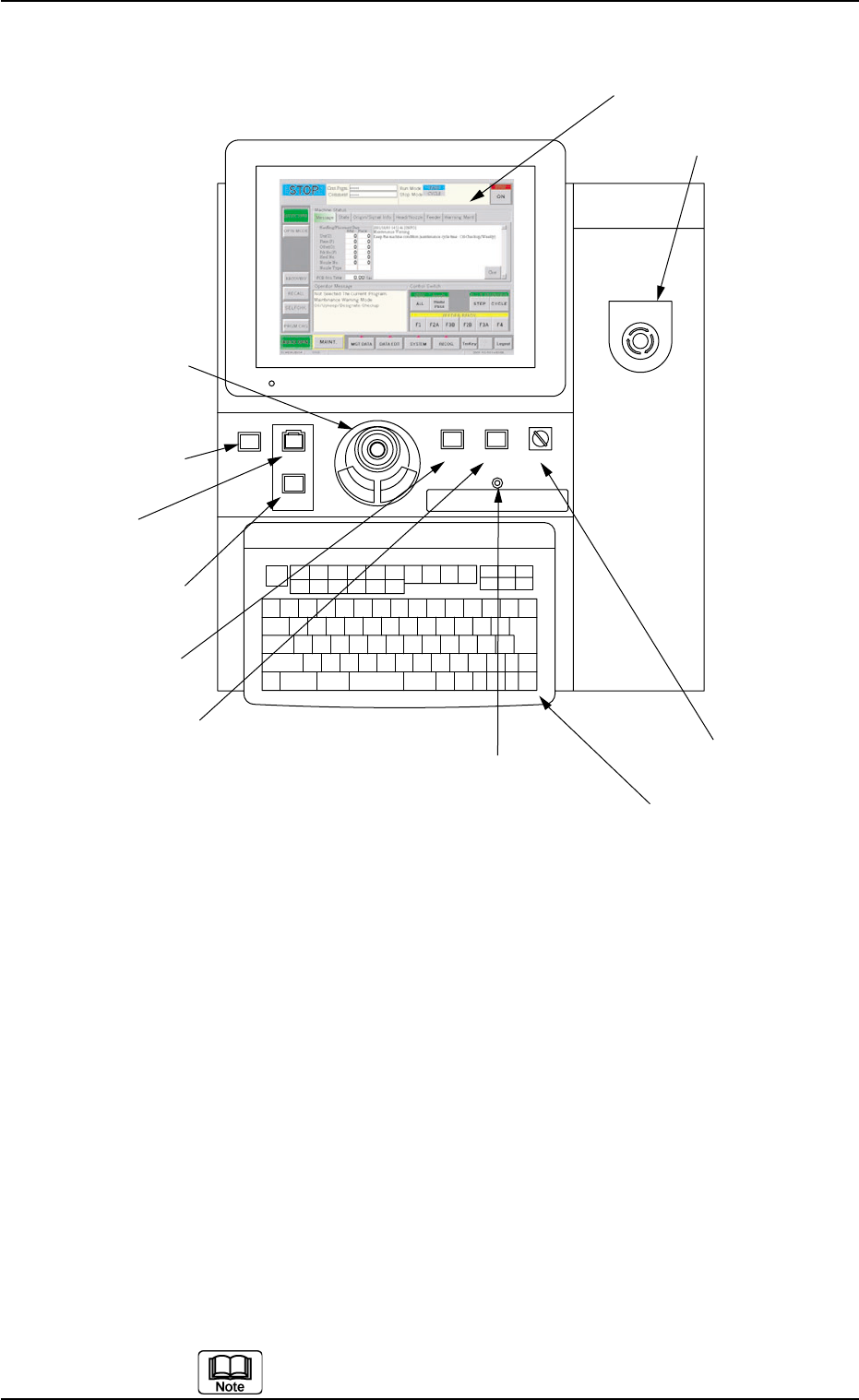
2.3.3 Front Operation Panel
Fig. 1A11
Arranged on the operation panel are switches and buttons required to
operate the machine.
The machine is provided with front and rear operation panels and can
be operated from either one of the panels. Panel selection is possible
with the [PNL CHANGE] buttons.
*1 [POWER ON] Button
• This button is used to turn on the power for operations.
*2 [START] Button
• This button is used to start the automatic operation.
The automatic operation can be started only when the lamp is flickering.
• While the lamp of this button is ON, it indicates that the machine is running
automatically.
When the [STOP] button is pressed during automatic operation, the lamp
extinguishes.
The lamp is kept ON while each device is being zeroed.
POWER ON
STOP
START
*1 [POWER ON] Button
*2 [START] Button
*3 [STOP] Button
*9 Keyboard
*8 [EMERGENCY STOP]
Switch
*7 [OPERATION] Switch
*5 [PNL CHANGE] Button
*4 [ENABLE] Button
*11 Front Touch Screen
*6 [LOCK] Lamp
*10 Pointing Device
EMERGENCY STOP
ENABLE
RUN SETUP
OPERATION
LOCK
PNL CHANGE
0307-005 1-12 AFO01EOPP
2.3 Operational Measures

*3 [STOP] Button
• This button is used to stop the automatic operation.
• When this button is pressed during X/Y table test, the test operation stops.
• When this button is pressed during zeroing operation, the zeroing opera-
tion of each device is interrupted, excluding the P.C.B. transfer.
*4 [ENABLE] Button
• When the [ON] button (entitled "MOVE") is pressed in the active operation
sheet, the lamp of the [ENABLE] button illuminates for two seconds. When
the [ENABLE] button is pressed with its lamp "ON", the machine performs
various operations selected in the operation sheets.
*5 [PNL CHANGE] Button
• This button is used to select either the front or the rear operation panel.
(a) The other operation panel can be selected by pressing the [PNL
CHANGE] button on the unavailable (invalid) side only when
the currently selected panel is not set in the "Operation Locked"
mode.
(b) While the LED of this button is ON, the followings become
available.
Front Touch Screen
[START] Button
[STOP] Button
[ENABLE] Button
[OPERATION] Switch
[EMERGENCY STOP] Switch
Pointing Device
Keyboard
(c) The [STOP] button and [EMERGENCY STOP] switch are al-
ways available regardless of the [PNL CHANGE] button.
(d) When the panel operation is not locked and the [STOP] button
on the unselected operation panel is pressed, the operation
panel on the pressed button side becomes activated automati-
cally.
• When this button is pressed with the LED being "ON", only the front opera-
tion panel becomes available in operations (Operation Locked) and the
[LOCK] lamps on both front and rear operation panels illuminate.
To cancel the "LOCK" mode, press this button again.
2.3 Operational Measures
0307-006 1-13 AFO01EOPP