1OM-1050-002.pdf - 第50页
4.2.2 Feeder Carriage Collision Error Detection Sensors When some feeder carriage collide with each other , these sensors are used to stop the machine. S en s o r N a me Symbol C o u n termeasures Carriage Collision 12 B…
4.2 Module Protection Sensors
This session describes the main sensors that are provided for ma-
chine protection.
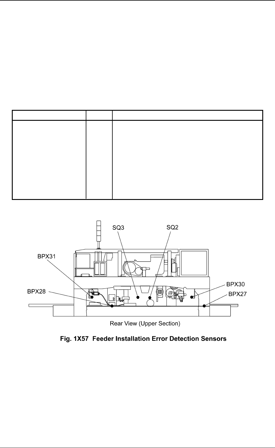
4.2.1 Feeder Installation Error Detection Sensors
When a tape feeder is not installed correctly, these sensors are used to prevent
the machine from being operated.
Sensor Name Symbol Countermeasures
Installation Error (+) BPX30
Installation Error (-) BPX31
Lifting Prevention (+) SQ2
Lifting Prevention (-) SQ3
Disengaged Latch (+) BPX27
Disengaged Latch (-) BPX28
4.2 Module Protection Sensors
Table 1X10
When one of the left sensors has detected an
error, the following measures are taken.
• The power to drive Feeder Carriages #1, #2,
#3, and #4 is shut off.
• The rotary turret stops after a cycle of opera-
tion.
Ref.: The rotary turret stops with its angle at
0° or 360°.
0301-003 47
AFO01EOPP
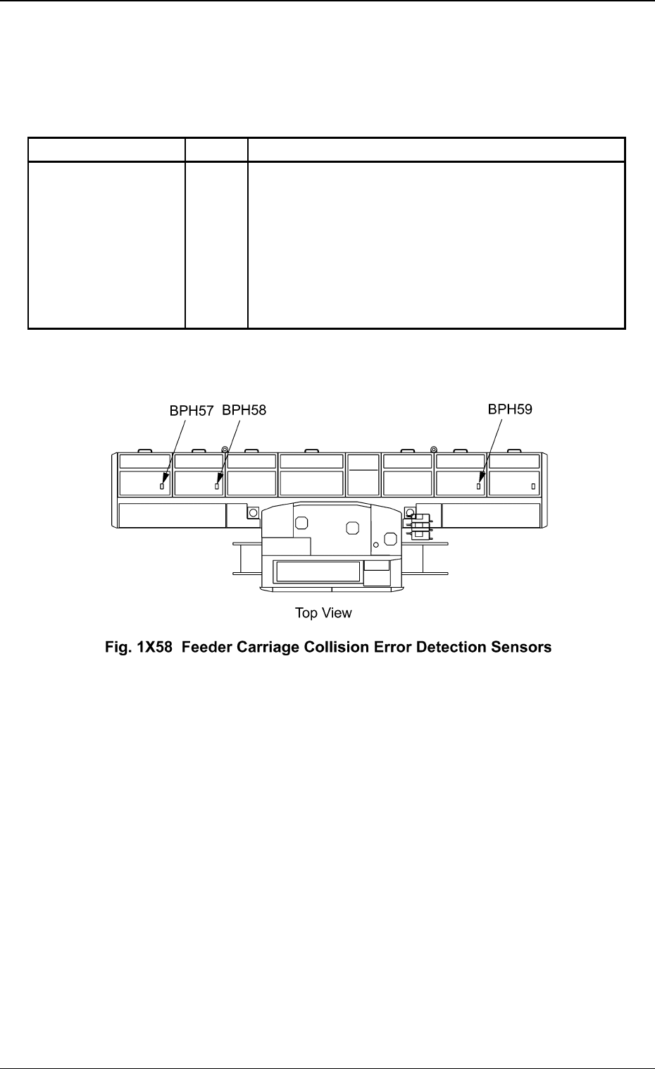
4.2.2 Feeder Carriage Collision Error Detection Sensors
When some feeder carriage collide with each other, these sensors are
used to stop the machine.
Sensor Name Symbol Countermeasures
Carriage Collision 12
BPH57
Carriage Collision 23 BPH58
Carriage Collision 34 BPH59
4.2 Module Protection Sensors
Table 1X11
When one of the left sensors has detected an error,
the following measures are taken.
• The power to drive Feeder Carriages #1, #2, #3,
and #4 is shut off.
• The rotary turret stops after a cycle of operation.
Ref.: The rotary turret stops with its angle at
0° or 360°.
0301-003 48
AFO01EOPP
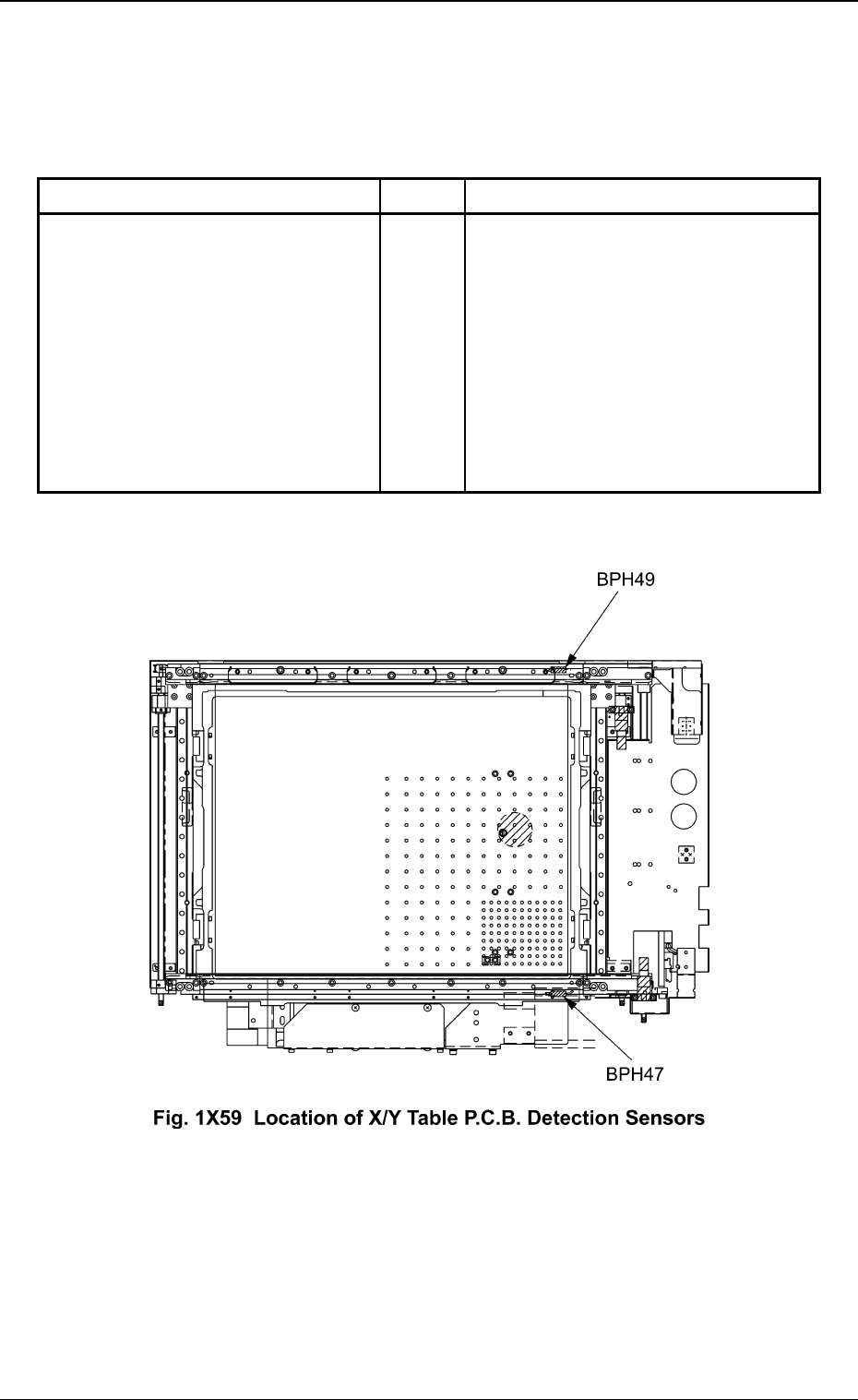
4.2.3 X/Y Table P.C.B. Detection Sensors
When a P.C.B. is not positioned correctly on the X/Y table, these sen-
sors are used to stop the machine.
Sensor Name Symbol Countermeasures
X/Y Table P.C.B. Detection (Fixed) BPH47
X/Y Table P.C.B. Detection (Movable) BPH49
4.2 Module Protection Sensors
Table 1X12
When one of the left sensors has de-
tected an error, the following mea-
sures are taken.
• The power to drive the X/Y table is
shut off.
• The rotary turret stops after a cycle
of operation.
Ref.: The rotary turret stops with its
angle at 0° or 360°.
0301-002 49
AFO01EOPP