1OM-1050-002.pdf - 第142页
3.2 Continuous Operation Disabled during Component Placement T able 1D7 Symptom The continuous operation became impossible during component placement. No error message is issued on the touch screen and the machine is kep…
3.1.2 During Pass Operation
Table 1D6
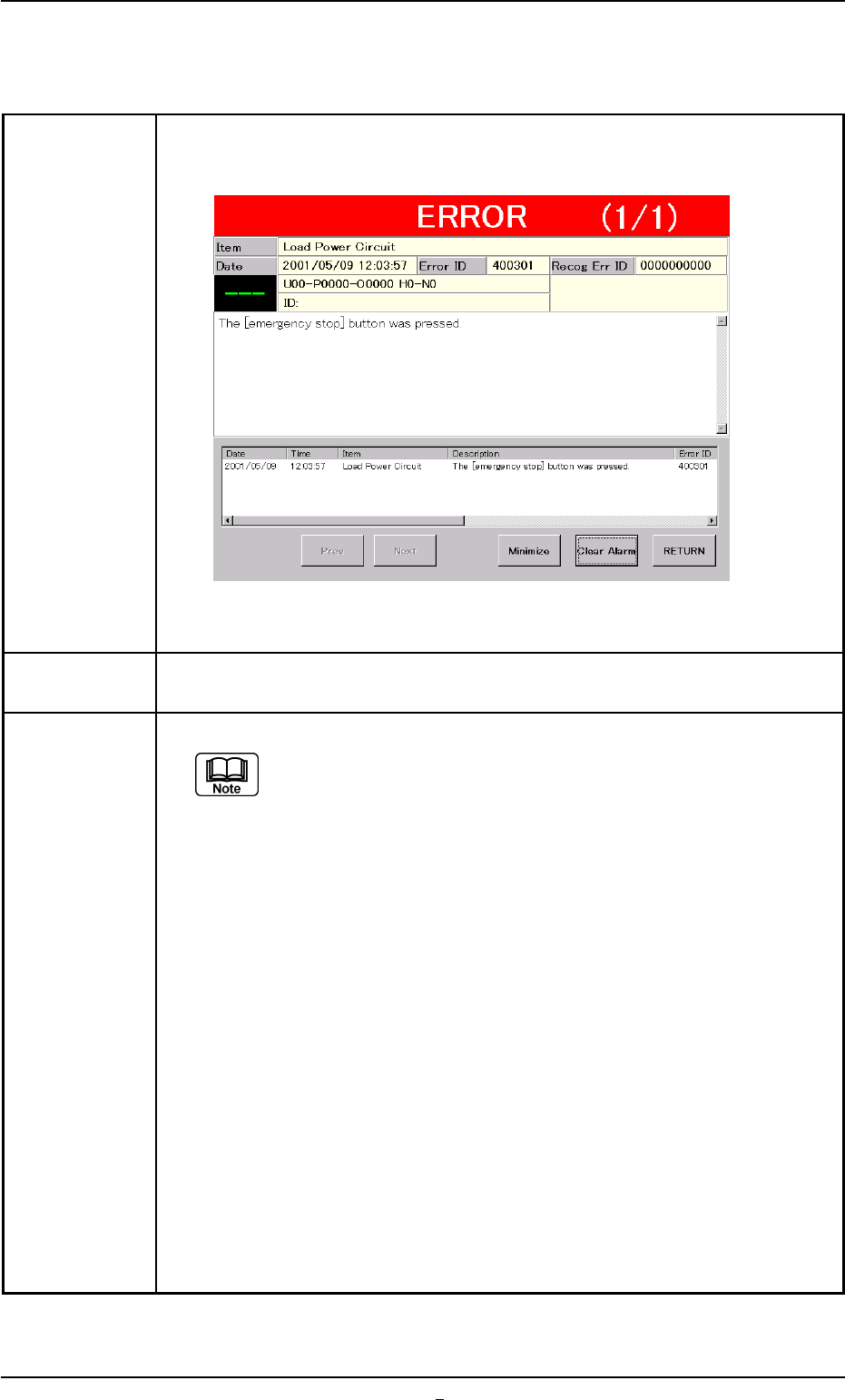
Symptom (1) The LED of the [POWER ON] button illuminates in red and the following
window opens.
Fig. 1D6-1
Cause (1) An [EMERGENCY STOP] switch was pressed.
Remedy (1) Press the [RETURN] button.
Remove the P.C.B. in the middle of passing inside the machine
if any.
(2) Unlock the [EMERGENCY STOP] switch.
(3) Hold down the [POWER ON] button for more than 1 second to re-supply
power to the machine.
• When the LED of the [POWER ON] button illuminates in yellowish
green, it indicates that the power is supplied to the machine.
When the LED is kept red, re-check the cause and remove it.
(4) Press the [ALL] button (entitled “ZERO") in the “AUTO OPN." window. In
2 seconds, press the [ENABLE] button on the operation panel to zero all
device.
0301-002 4-5-1 AFO01EOPP
3.1 [EMERGENCY STOP] Switch Pressed
3.2 Continuous Operation Disabled during Component
Placement
Table 1D7
Symptom The continuous operation became impossible during component placement.
No error message is issued on the touch screen and the machine is kept in
the "RUN" or the "WAIT" mode without any movement.
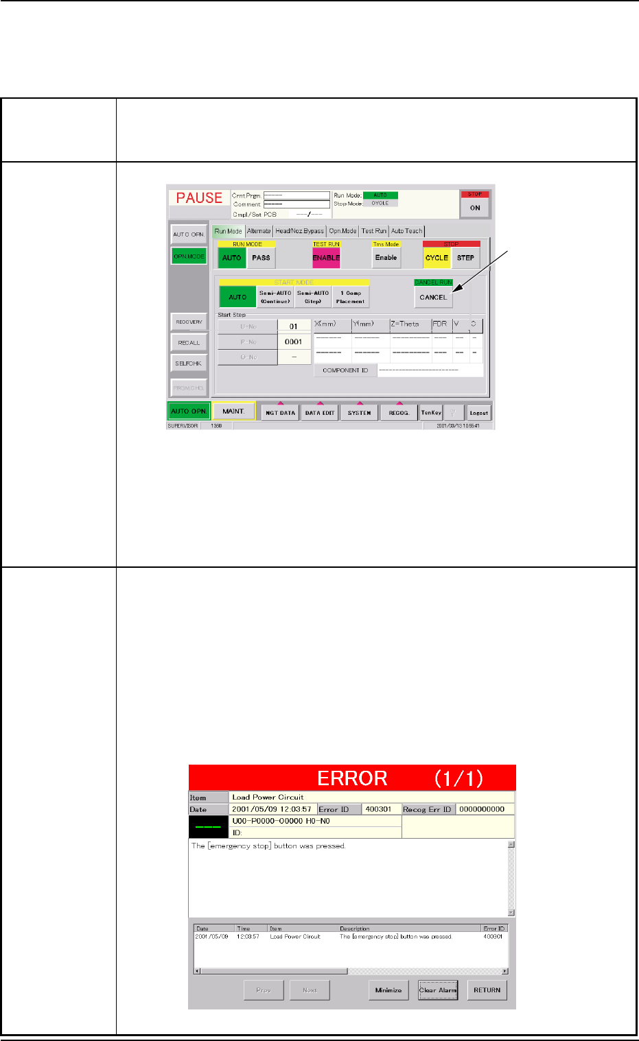
Cause (Cause 1) The [CANCEL] button was pressed.
Fig. 1D7 "Opn. Mode" Tab Sheet ("PAUSE" Mode)
(Cause 2) A timing error has occurred.
An interlock error has occurred.
The machine stopped at an emergency although the cause is un-
known.
Remedy When a normal restart operation is performed after the continuous operation
has become impossible during component placement, the P.C.B. in the middle
of process is discharged to the output machine, producing a defective P.C.B.
Therefore, it is required to perform the following "Warm Start" operation to set
the machine to its normal condition.
(1) Press an [EMERGENCY STOP] switch.
The "ERROR" window opens.
(2) Confirm that the message "The [emergency stop] button was pressed."
has appeared on the screen.
Fig. 1D8 "ERROR" Window
[CANCEL] button
3.2 Continuous Operation Disabled during Component Placement
0301-004 4 - 6 AFO01EOPP
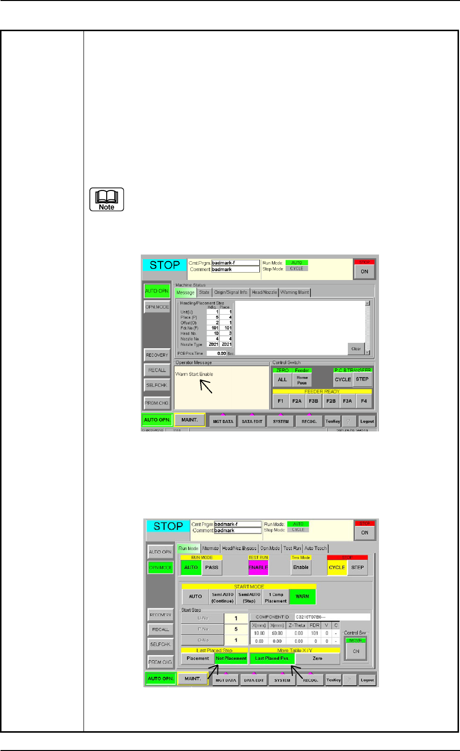
Table 1D8
(3) Press the [RETURN] button in the "ERROR" window. The "ERROR" win-
dow closes.
(4) Press the [ALL] button (entitled "ZERO") in the "AUTO OPN." window to
zero all axis.
(5) Check whether or not the P.C.B. in the middle of component placement is
located out of the positioning section on the X/Y table or the components
are normally placed (not dispersed).
(6) When the message "Warm Start Enable" is displayed in the "Operator
Message" pane in the "AUTO OPN." window, it means that the "Warm
Start" operation is feasible.
(a) "Warm Start Enable" means that the production is interrupted in
the middle of component placement.
(b) When the operation is interrupted without any component being
placed, "Warm Start" becomes impossible.
Fig. 1D9 "AUTO OPN." Window (Submenu)
(7) Press the [OPN. MODE] button on the submenu bar. The "OPN. MODE"
window (submenu) opens.
Fig. 1D10 "AUTO OPN." Window (Warm Start Available Mode)
0210-004 4 - 7 AFO01EOPP
3.2 Continuous Operation Disabled during Component Placement