1OM-1050-002.pdf - 第46页
4.1.3 [Feeder Work Area Safety Door] Switches Each feeder work area safety door is provided with a [Feeder Work Area Safety Door] switch inside as shown below . Fig. 1X55 Fig. 1X54 [Feeder Work Area Safety Door] Switches…
4.1 Safety Switches
Switch Name Countermeasures
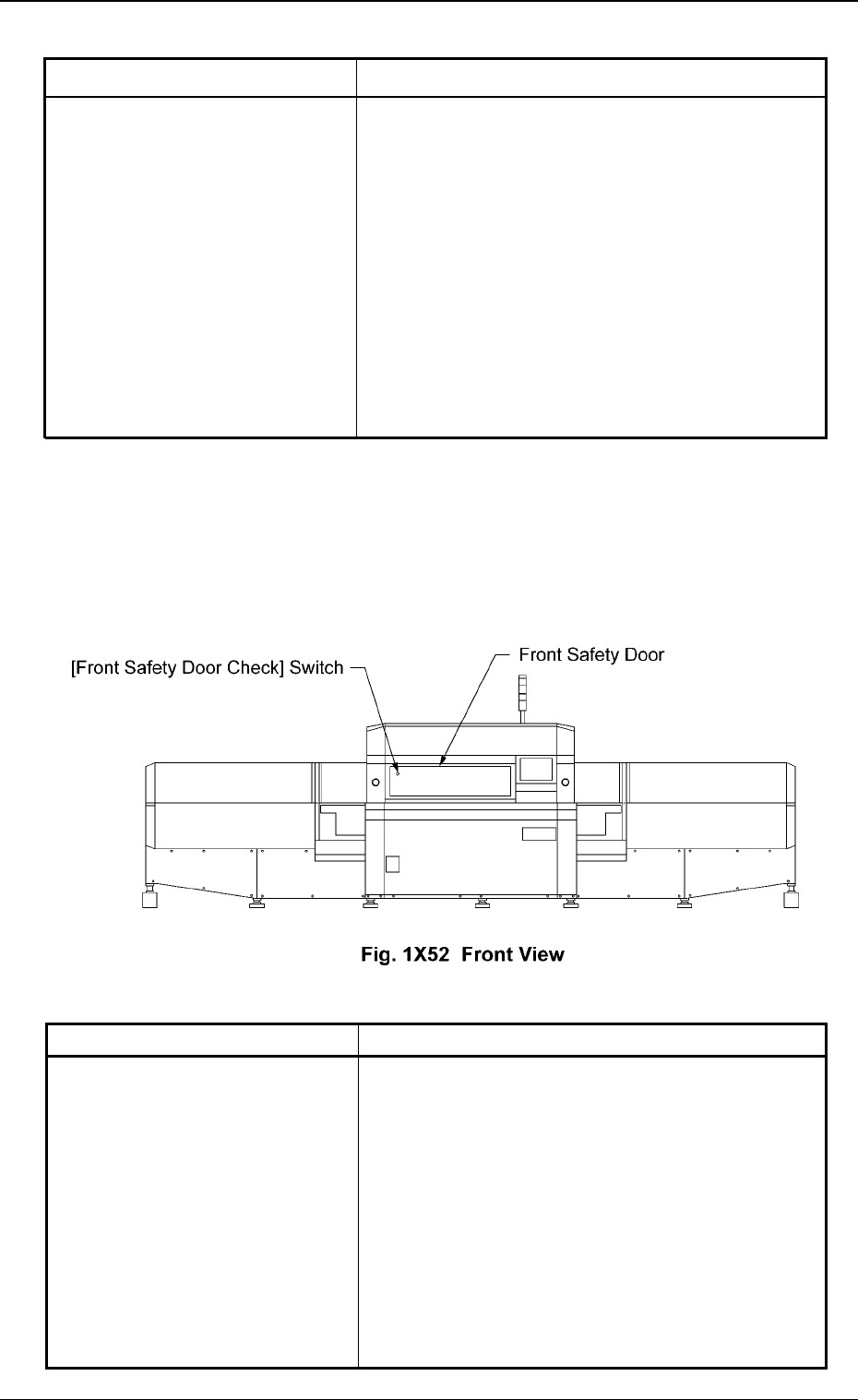
4.1.2 [Front Safety Door Check] Switch
When the front safety door is opened with the [OPERATION] switch set
to "RUN", the switch is activated and an error occurs.
When the switch is set to "SETUP", it is not activated.
Table 1X7
Switch Name Countermeasures
Table 1X6
[EMERGENCY STOP] Switch (1)
[EMERGENCY STOP] Switch (2)
[EMERGENCY STOP] Switch (3)
[EMERGENCY STOP] Switch (4)
Pressing one of the [EMERGENCY STOP]
switches cuts power to the following modules.
• All power sources for loads are shut off.
The power supply to the mechanisms of all mo-
tor shafts and 24-voltage loads in the solenoid
system (SOL and SV) is shut off.
Note: The load power supply for the vacuum
pump and the DD motor is excluded. The
control power supply for the control boards
and sensors is also excluded.
When the front safety door is opened, the following
measures are taken.
• All power sources for loads are shut off.
The power supply to the mechanisms of all mo-
tor shafts and 24-voltage loads in the solenoid
system (SOL and SV) is shut off.
Note: The load power supply for the vacuum
pump and the DD motor is excluded.
The control power supply for the control
boards and sensors is also excluded.
[Front Safety Door Check] Switch
0301-006 43 AFO01EOPP
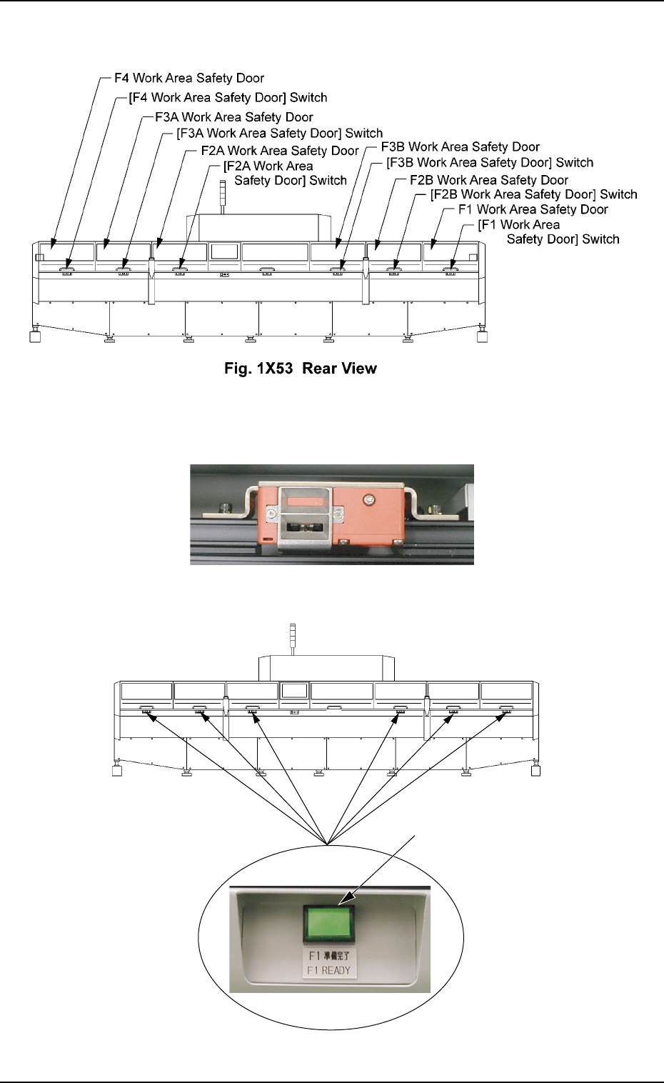
4.1.3 [Feeder Work Area Safety Door] Switches
Each feeder work area safety door is provided with a [Feeder Work
Area Safety Door] switch inside as shown below.
Fig. 1X55
Fig. 1X54 [Feeder Work Area Safety Door] Switches
[FEEDER READY] Buttons
4.1 Safety Switches
0210-004 44 AFO01EOPP

Switch Name Countermeasures
(a) When the lamp of the [READY] button is "OFF", the [Work
Area Safety Door] switch is released, making it possible to
supply components.
Confirm that the lamp of the [FEEDER READY] button is
"OFF" and then open the safety door.
(b) When the machine is in the emergency stop mode (load
power shut off), the lamp of the [READY] button extin-
guishes and the electromagnetic lock of the work area
safety door is released exceptionally although the feeder
carriage is not located in the work area.
4.1 Safety Switches
[F1 Work Area Safety Door] Switch
[F2A Work Area Safety Door] Switch
[F3B Work Area Safety Door] Switch
[F2B Work Area Safety Door] Switch
[F3A Work Area Safety Door] Switch
[F4 Work Area Safety Door] Switch
Table 1X8
• When the feeder carriage is located in the
work area and the work area safety door in
the work area is opened, the power to drive
the feeder carriage is shut off.
Ref.: The lamp of the [READY] button ex-
tinguishes.
• When the feeder carriage is not located in
the work area, the [Work Area Safety Door]
switch in the work area is activated, pre-
venting the safety door from being opened.
Ref.:The lamp of the [READY] button
illuminates.
Should the safety door opens at this
time, the power to drive the feeder car-
riages (F1 through F4) is shut off.
• While the work area safety door is kept
open, the feeder carriage is prohibited from
any movement such as zeroing and manual
alignment operations, etc.
0301-003 45 AFO01EOPP