1OM-1050-002.pdf - 第144页
T able 1D9 (a) When the "W arm Start" operation is feasible, the [W ARM] button appears in the "OPN. MODE" window (submenu). (b) When the [W ARM] button is not displayed, it means that the "W arm…
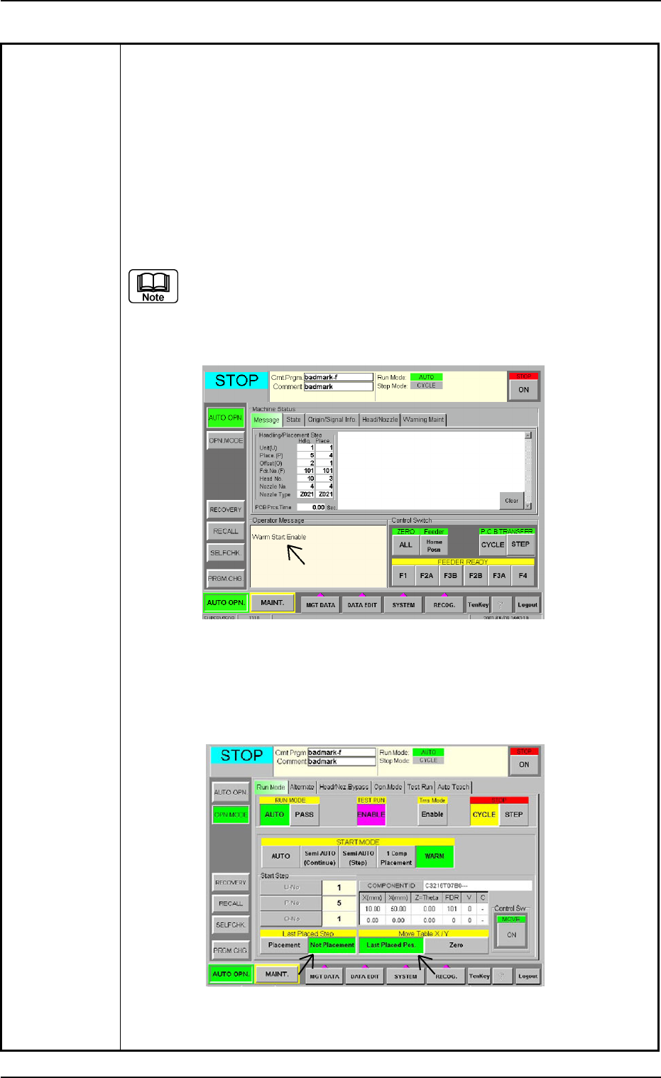
Table 1D8
(3) Press the [RETURN] button in the "ERROR" window. The "ERROR" win-
dow closes.
(4) Press the [ALL] button (entitled "ZERO") in the "AUTO OPN." window to
zero all axis.
(5) Check whether or not the P.C.B. in the middle of component placement is
located out of the positioning section on the X/Y table or the components
are normally placed (not dispersed).
(6) When the message "Warm Start Enable" is displayed in the "Operator
Message" pane in the "AUTO OPN." window, it means that the "Warm
Start" operation is feasible.
(a) "Warm Start Enable" means that the production is interrupted in
the middle of component placement.
(b) When the operation is interrupted without any component being
placed, "Warm Start" becomes impossible.
Fig. 1D9 "AUTO OPN." Window (Submenu)
(7) Press the [OPN. MODE] button on the submenu bar. The "OPN. MODE"
window (submenu) opens.
Fig. 1D10 "AUTO OPN." Window (Warm Start Available Mode)
0210-004 4 - 7 AFO01EOPP
3.2 Continuous Operation Disabled during Component Placement
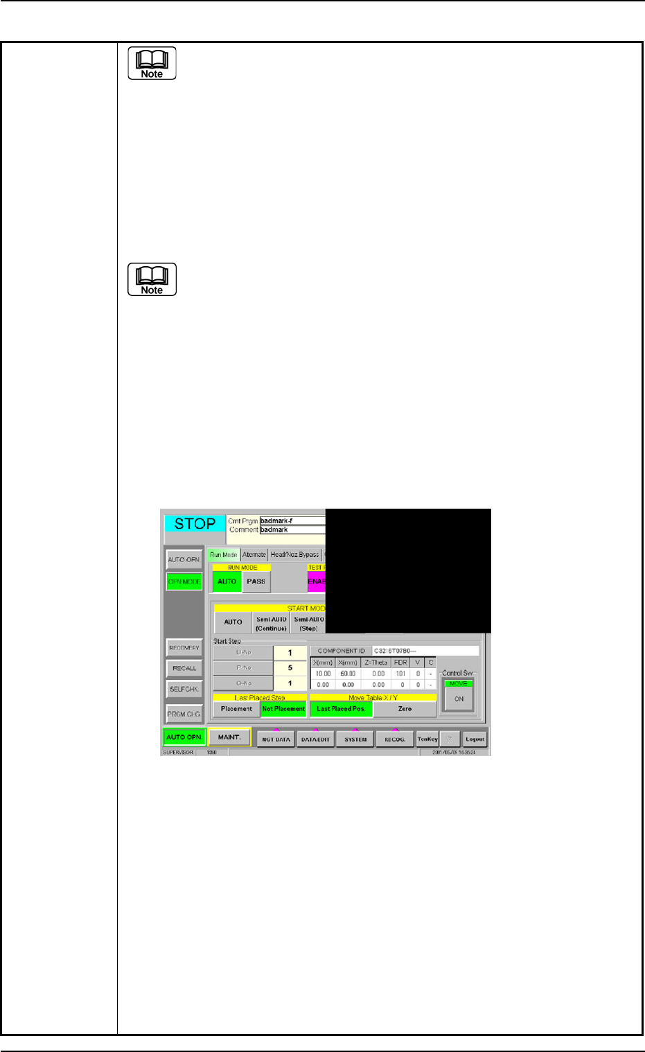
Table 1D9
(a) When the "Warm Start" operation is feasible, the [WARM] button
appears in the "OPN. MODE" window (submenu).
(b) When the [WARM] button is not displayed, it means that the "Warm
Start" operation is not feasible or there was a mistake in the re-
medial procedure after an error had occurred. In this case, per-
form the semi-automatic operation (step designation) to reset the
machine to its normal condition.
(8) Check how the last component was placed when the operation was inter-
rupted.
The last placement step is indicated in the "Start Step" group box in
the "OPN. MODE" window (submenu).
Check visually whether or not the relevant component is placed on
the P.C.B.
(9) Press the [Last Placed Pos.] button (entitled "Move Table X/Y") in the "OPN.
MODE" window (submenu).
(10) Press the [RECOG.] button on the main menu bar and make the recog-
nition window (1/4 of the whole view at the upper right corner) appear.
(11) Press the [ON] button (entitled "MOVE"). In two seconds, press the [EN-
ABLE] button on the operation panel.
The last placement position is displayed as a recognition image.
Fig. 1D11 "OPN. MODE" Window (Last Step Confirmation)
(12) Check whether or not the component is placed. If not, select the [Place-
ment] button. If the component is already placed, select the [Not Place-
ment] button.
(13) Press the [Zero] button (entitled "Move Table X/Y") and press the [ON]
button (entitled "MOVE"). In two seconds, press the [ENABLE] button on
the operation panel. The X/Y Table is zeroed.
(14) Press the [START] button on the operation panel. The "Warm Start" op-
eration is implemented.
(15) As for the P.C.B. produced through "Warm Start" operations, be sure to
confirm that all components are correctly placed.
0207-003 4 - 8
AFO01EOPP
3.2 Continuous Operation Disabled during Component Placement

1st Edition Issued May, 2003 Copying Prohibited
2nd Edition Issued Jul., 2003
Compiled and Distributed by
0307-002
AFO01EOPP