1OM-1050-002.pdf - 第48页
4.1.4 [FEEDER CARRIAGE COVER] Safety Switch Fig. 1X56 Rear View The [FEEDER CARRIAGE COVER] safety switch is mounted inside the cover as shown below . Switch Name Countermeasures 4.1 Safety Switches Fig. 1X56-1 T able 1X…
Switch Name Countermeasures
(a) When the lamp of the [READY] button is "OFF", the [Work
Area Safety Door] switch is released, making it possible to
supply components.
Confirm that the lamp of the [FEEDER READY] button is
"OFF" and then open the safety door.
(b) When the machine is in the emergency stop mode (load
power shut off), the lamp of the [READY] button extin-
guishes and the electromagnetic lock of the work area
safety door is released exceptionally although the feeder
carriage is not located in the work area.
4.1 Safety Switches
[F1 Work Area Safety Door] Switch
[F2A Work Area Safety Door] Switch
[F3B Work Area Safety Door] Switch
[F2B Work Area Safety Door] Switch
[F3A Work Area Safety Door] Switch
[F4 Work Area Safety Door] Switch
Table 1X8
• When the feeder carriage is located in the
work area and the work area safety door in
the work area is opened, the power to drive
the feeder carriage is shut off.
Ref.: The lamp of the [READY] button ex-
tinguishes.
• When the feeder carriage is not located in
the work area, the [Work Area Safety Door]
switch in the work area is activated, pre-
venting the safety door from being opened.
Ref.:The lamp of the [READY] button
illuminates.
Should the safety door opens at this
time, the power to drive the feeder car-
riages (F1 through F4) is shut off.
• While the work area safety door is kept
open, the feeder carriage is prohibited from
any movement such as zeroing and manual
alignment operations, etc.
0301-003 45 AFO01EOPP
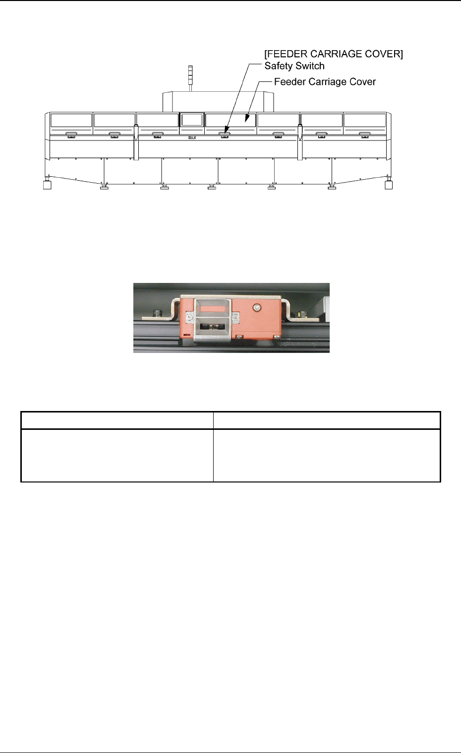
4.1.4 [FEEDER CARRIAGE COVER] Safety Switch
Fig. 1X56 Rear View
The [FEEDER CARRIAGE COVER] safety switch is mounted inside
the cover as shown below.
Switch Name Countermeasures
4.1 Safety Switches
Fig. 1X56-1
Table 1X9
[FEEDER CARRIAGE COVER] Safety
Switch
• The power for operations cannot be sup-
plied with the feeder carriage cover being
open.
0210-002 46 AFO01EOPP
4.2 Module Protection Sensors
This session describes the main sensors that are provided for ma-
chine protection.
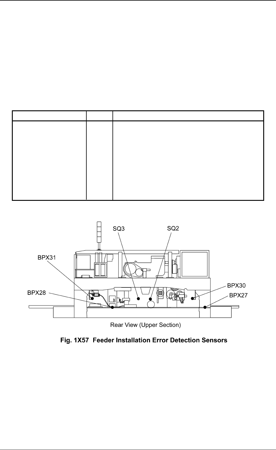
4.2.1 Feeder Installation Error Detection Sensors
When a tape feeder is not installed correctly, these sensors are used to prevent
the machine from being operated.
Sensor Name Symbol Countermeasures
Installation Error (+) BPX30
Installation Error (-) BPX31
Lifting Prevention (+) SQ2
Lifting Prevention (-) SQ3
Disengaged Latch (+) BPX27
Disengaged Latch (-) BPX28
4.2 Module Protection Sensors
Table 1X10
When one of the left sensors has detected an
error, the following measures are taken.
• The power to drive Feeder Carriages #1, #2,
#3, and #4 is shut off.
• The rotary turret stops after a cycle of opera-
tion.
Ref.: The rotary turret stops with its angle at
0° or 360°.
0301-003 47
AFO01EOPP