1OM-1050-002.pdf - 第63页
(a) Unless the lamp of the [FEEDER READY] button illumi- nates, the automatic operation cannot be started. While the lamp of the [FEEDER READY] button is ON, the feeder work area safety door is locked and cannot be opene…
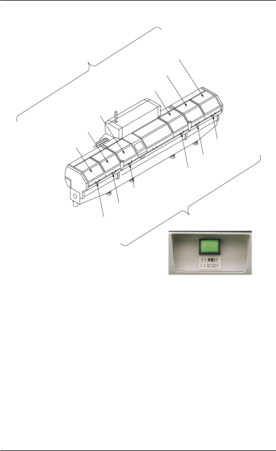
2.2.5 [FEEDER READY] Buttons
Fig. 1A8 [FEEDER READY] Buttons
••
••
• The [FEEDER READY] buttons are used to inform the machine that
the tape feeders on the feeder carriages are set ready for use after
replacement or component replenishment.
One feeder carriage section is provided with a pair of [FEEDER
READY] button and feeder work area safety door.
••
••
• When the related [FEEDER READY] button is pressed after the tape
feeders are installed on the feeder carriage, the feeder work area
safety door is locked (opening prohibited) and the lamp of the button
illuminates, indicating that the feeder carriage is set ready for use.
2.2 Safety Devices
0102-002 1-8 AFO01EOPP
F1 Work Area Safety Door
[F1 READY] Button
Feeder Work Area
Safety Door
F2A Work Area Safety Door
F3B Work Area Safety Door
F2B Work Area Safety Door
F3A Work Area Safety Door
F4 Work Area Safety Door
[F2A READY] Button
[F3B READY] Button
[F2B READY] Button
[F3A READY] Button
[F4 READY] Button
Feeder Ready Buttons

(a) Unless the lamp of the [FEEDER READY] button illumi-
nates, the automatic operation cannot be started. While
the lamp of the [FEEDER READY] button is ON, the feeder
work area safety door is locked and cannot be opened.
(b) When the [FEEDER READY] button is pressed right after
the feeder work area safety door is closed, the lamp may
not illuminate soon. This is not trouble. In this case, just
press the [FEEDER READY] button again.
(c) When a component shortage error occurs during automatic
operation, the feeder carriage moves to the work area and
the lamp of the [FEEDER READY] button related to the
error-caused feeder carriage extinguishes.
After completion of feeder replacement or component sup-
ply replenishment, press the [FEEDER READY] button to
set the feeder carriage ready for use.
2.2 Safety Devices
0102-002 1-9 AFO01EOPP
2.3 Operational Measures
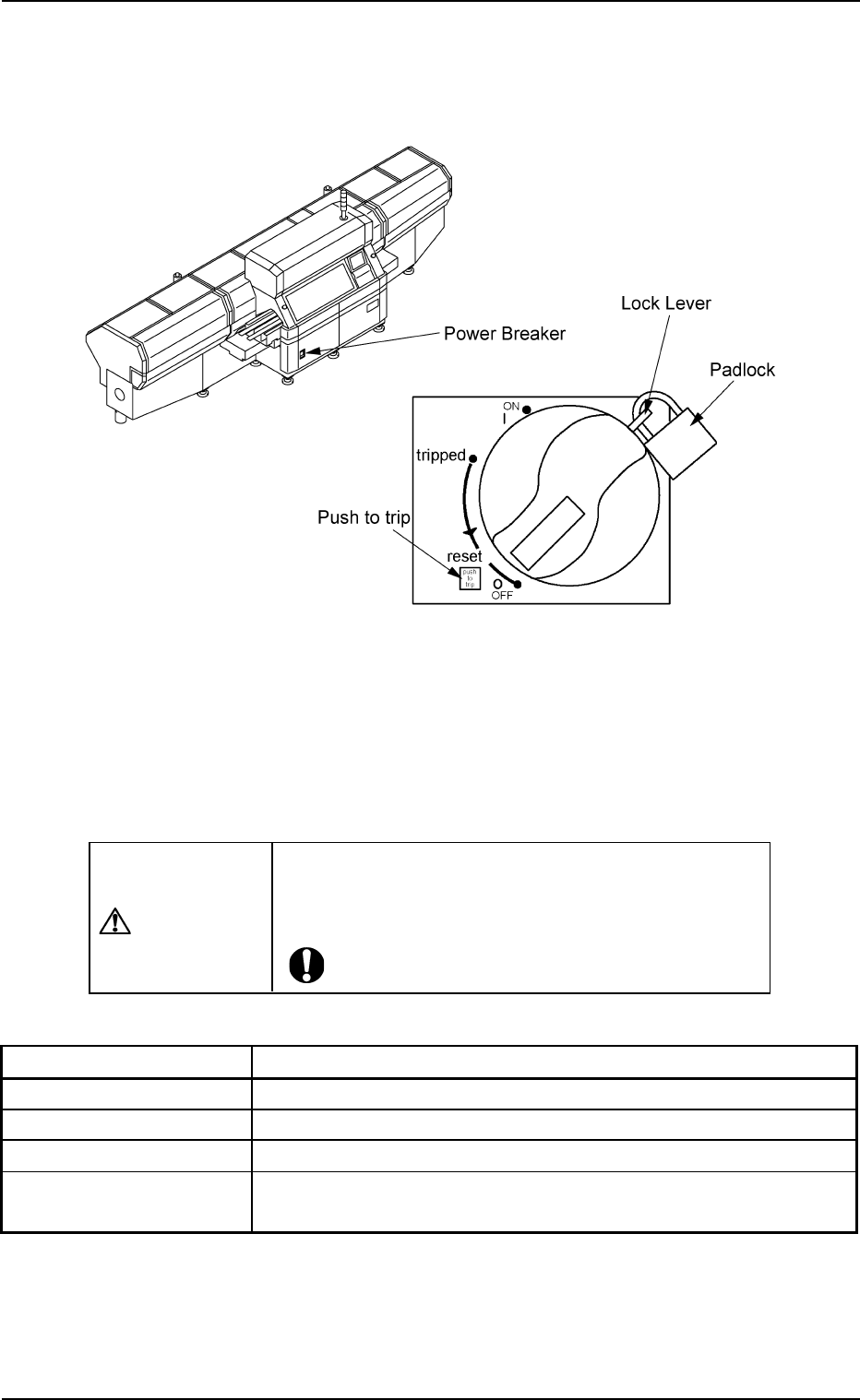
2.3.1 Power Breaker
Fig. 1A9
The power breaker is provided to supply or shut off power to the machine.
The power breaker can be locked with a padlock.
Refer to "1.7.2 Locking the Power Breaker with the Padlock" in "Section
3 Scope of Automatic Operation" of "Volume 1: Operation (Operator)"
for the procedure to lock the breaker.
CAUTION
Before maintenance, etc., be sure to turn off the power
breaker and lock it with the padlock for safety pur-
poses.
Table 1A1
Symbols/Names Functions
|(OFF) Power OFF (Fig. 1A9)
tripped Power Interception due to Overcurrent
|(ON) Power Supplied
Push to trip Test Button for Power Interception (caused by
overcurrent)
2.3 Operational Measures
0207-004 1-10 AFO01EOPP