1OM-1050-002.pdf - 第76页
*4 [ENABLE] Button • When the [ON] button (entitled "MOVE") is pressed in the active operation sheet, the lamp of the [ENABLE] button illuminates for two seconds. When the [ENABLE] button is pressed with its la…
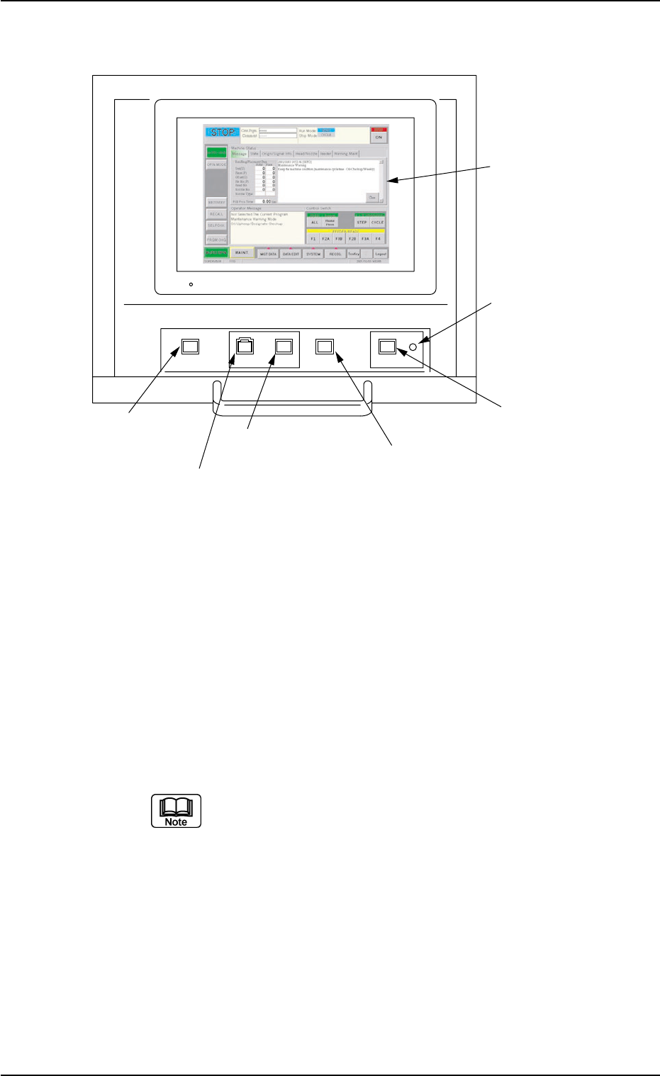
2.3.4 Rear Operation Panel
Fig. 1A15
*1 [POWER ON] Button
• This button is used to turn on the power for operations.
*2 [START] Button
• This button is used to start the automatic operation.
The automatic operation can be started only when the lamp is flickering.
• While the lamp of this button is ON, it indicates that the machine is running
automatically.
When the [STOP] button is pressed during automatic operation, the LED
of this button extinguishes.
The lamp is kept ON while each device is being zeroed.
*3 [STOP] Button
• This button is used to stop the automatic operation.
• When this button is pressed during X/Y table test, the test operation stops.
• When this button is pressed during zeroing operation, the zeroing opera-
tion of each device is interrupted, excluding the P.C.B. transfer.
0207-004 1-18
AFO01EOPP
POWER ON START STOP
ENABLE
PNL CHANGE LOCK
*1 [POWER ON] Button
*2 [START] Button
*3 [STOP] Button
*4 [ENABLE] Button
*5 [PNL CHANGE] Button
*6 [LOCK] Lamp
*7 Rear Touch Screen
2.3 Operational Measures

*4 [ENABLE] Button
• When the [ON] button (entitled "MOVE") is pressed in the active operation
sheet, the lamp of the [ENABLE] button illuminates for two seconds. When
the [ENABLE] button is pressed with its lamp "ON", the machine performs
various operations selected in the operation sheets.
*5 [PNL CHANGE] Button
• This button is used to select either the front or the rear operation panel.
(a) The other operation panel can be selected by pressing the [PNL
CHANGE] button on the unavailable (invalid) side only when
the currently selected panel is not set in the "Operation Locked"
mode.
(b) While the LED of this button is ON, the followings become
available.
Rear Touch Screen
[START] Button
[STOP] Button
[ENABLE] Button
(c) The [STOP] button can be activated anytime regardless of the
[PNL CHANGE] button.
(d) When the panel operation is not locked and the [STOP] button
on the unselected operation panel is pressed, the operation
panel on the pressed button side becomes activated automati-
cally.
• When this button is pressed with the LED being "ON", only the rear opera-
tion panel becomes available in operations (Operation Locked) and the
[LOCK] lamps on both front and rear operation panels illuminate.
To cancel the "LOCK" mode, press this button again.
*6 [LOCK] Lamp
• While the lamp is ON, it indicates that the selected operation is locked.
• When the operation panel is operated from the unavailable side, the [LOCK]
lamp flickers.
To cancel the flickering of the lamp, press the [PNL CHANGE] button and
follow the steps to set the operation-lock mode again.
*7 Rear Touch Screen
• The operation windows will be displayed on the rear touch screen as well
as the front one.
Various types of operations become available by touching the buttons and
tabs on the screen.
2.3 Operational Measures
0207-004 1-19 AFO01EOPP
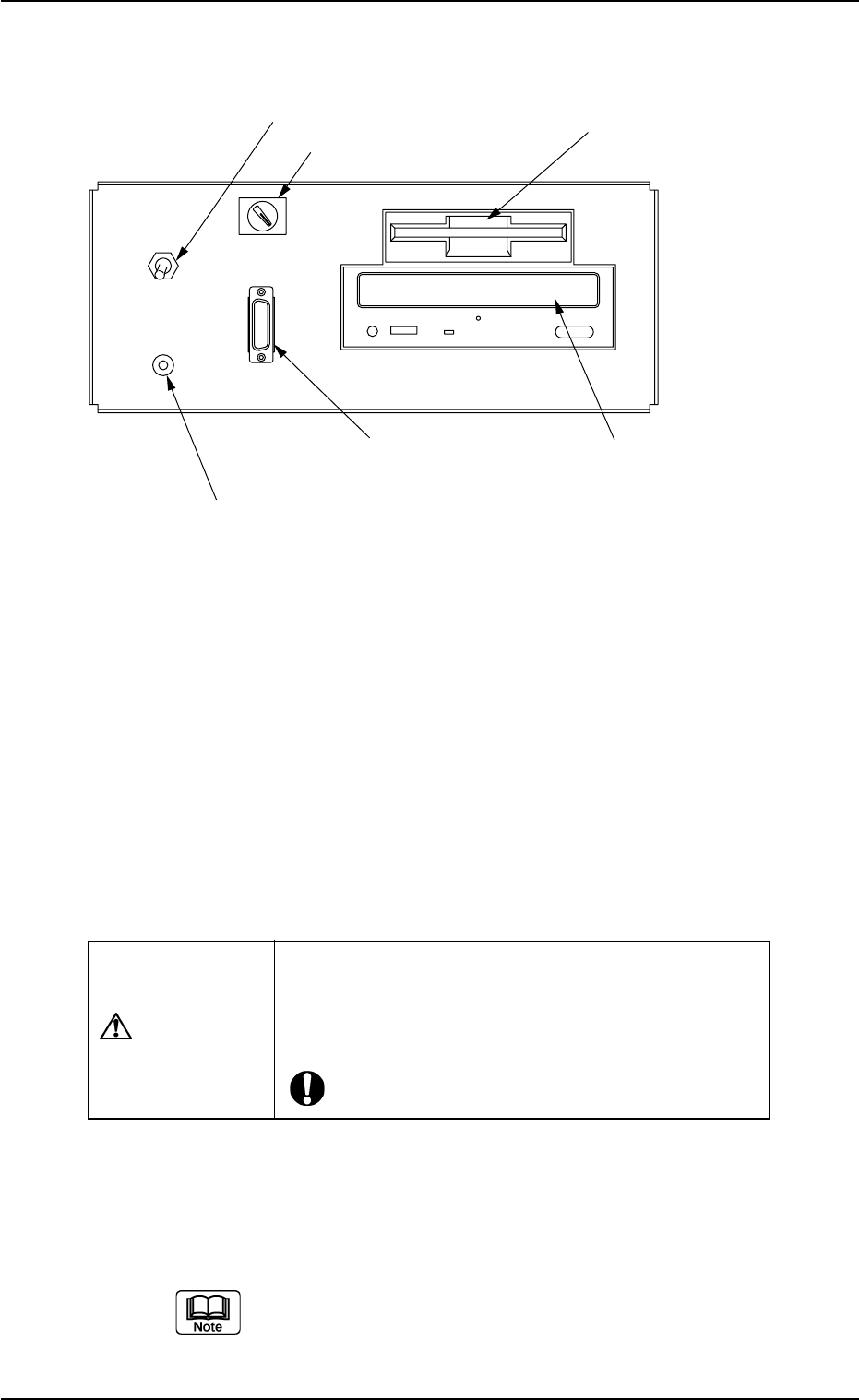
2.3.5 Front Service Panel
Fig. 1A16
*1 Working Lamp Switch
This switch is used to turn on or off the working spot lamp.
*2 Ground Terminal for Wrist Band
This terminal is used to clear a ground through the wrist band.
*3 Selector Switch
This switch is used to select either the operation panel "OFF" of the
main machine or the secondary operation panel "ON" for mainte-
nance.
CAUTION
Keep the selector switch "OFF" during automatic op-
eration.
When the switch is turned "ON", the power will be
cut off.
*4 Connector for Secondary Operation Panel
This connector is used to connect the secondary operation panel
for maintenance.
This connector is provided only for a service personnel.
ON OFF
LIGHT
FDD
CD-ROMD
OPE-TAB
*3 Selector Switch
*1 Working Lamp
Switch
*2 Ground Terminal
for Wrist Band
*5 Floppy Disk Drive
*4 Connector for Secondary
Operation Panel
*6 CD-ROM Drive
0207-004 1-20 AFO01EOPP
2.3 Operational Measures