1OM-1050-002.pdf - 第65页
2.3.2 Light T ower Fig. 1A10 The light tower indicates the condition of the machine with the lamps and buzzer sounds. Lamp Colors The machine is factory-adjusted upon shipment. T able 1A2 Lamp Colors Machine Condition Re…
2.3 Operational Measures
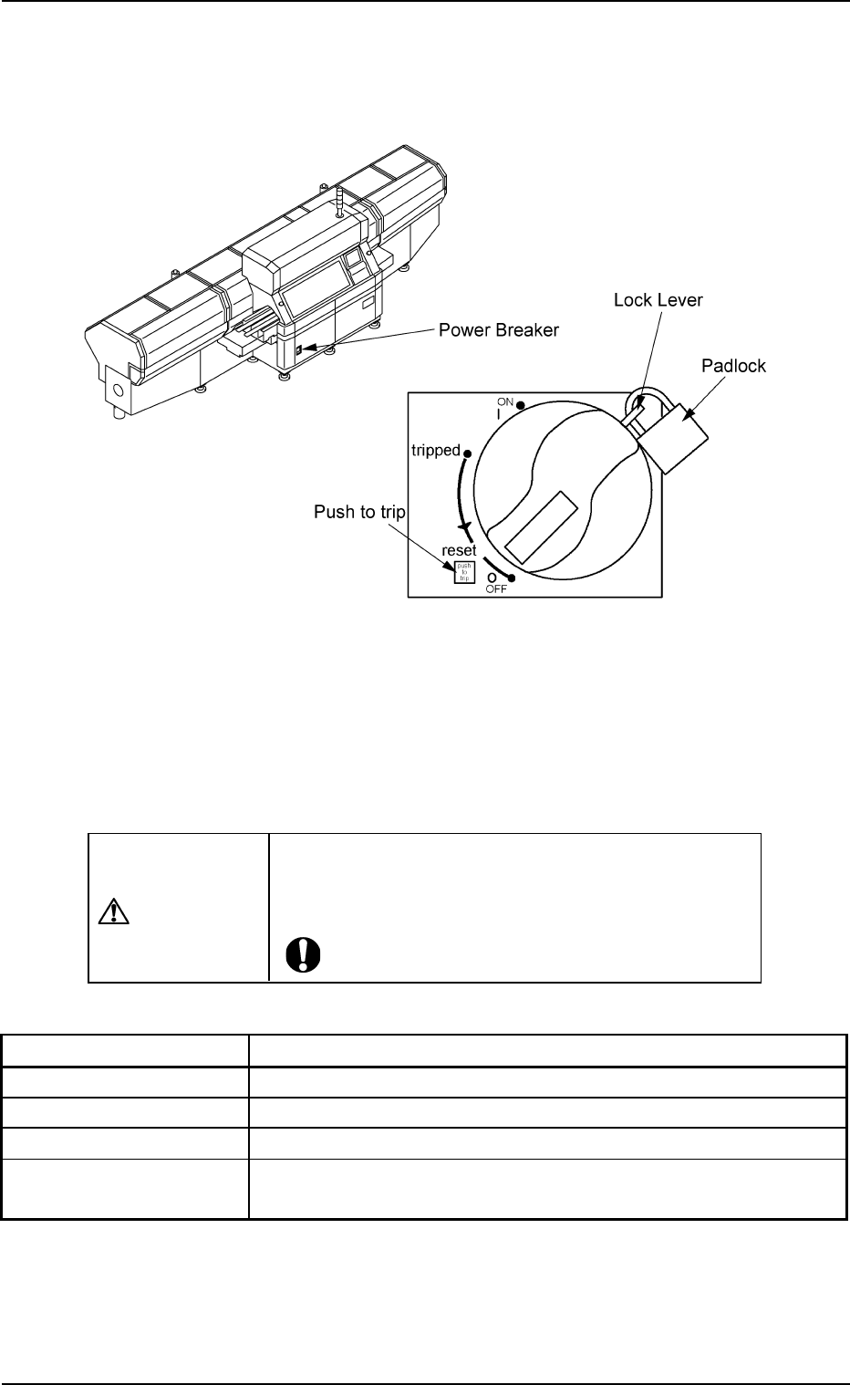
2.3.1 Power Breaker
Fig. 1A9
The power breaker is provided to supply or shut off power to the machine.
The power breaker can be locked with a padlock.
Refer to "1.7.2 Locking the Power Breaker with the Padlock" in "Section
3 Scope of Automatic Operation" of "Volume 1: Operation (Operator)"
for the procedure to lock the breaker.
CAUTION
Before maintenance, etc., be sure to turn off the power
breaker and lock it with the padlock for safety pur-
poses.
Table 1A1
Symbols/Names Functions
|(OFF) Power OFF (Fig. 1A9)
tripped Power Interception due to Overcurrent
|(ON) Power Supplied
Push to trip Test Button for Power Interception (caused by
overcurrent)
2.3 Operational Measures
0207-004 1-10 AFO01EOPP
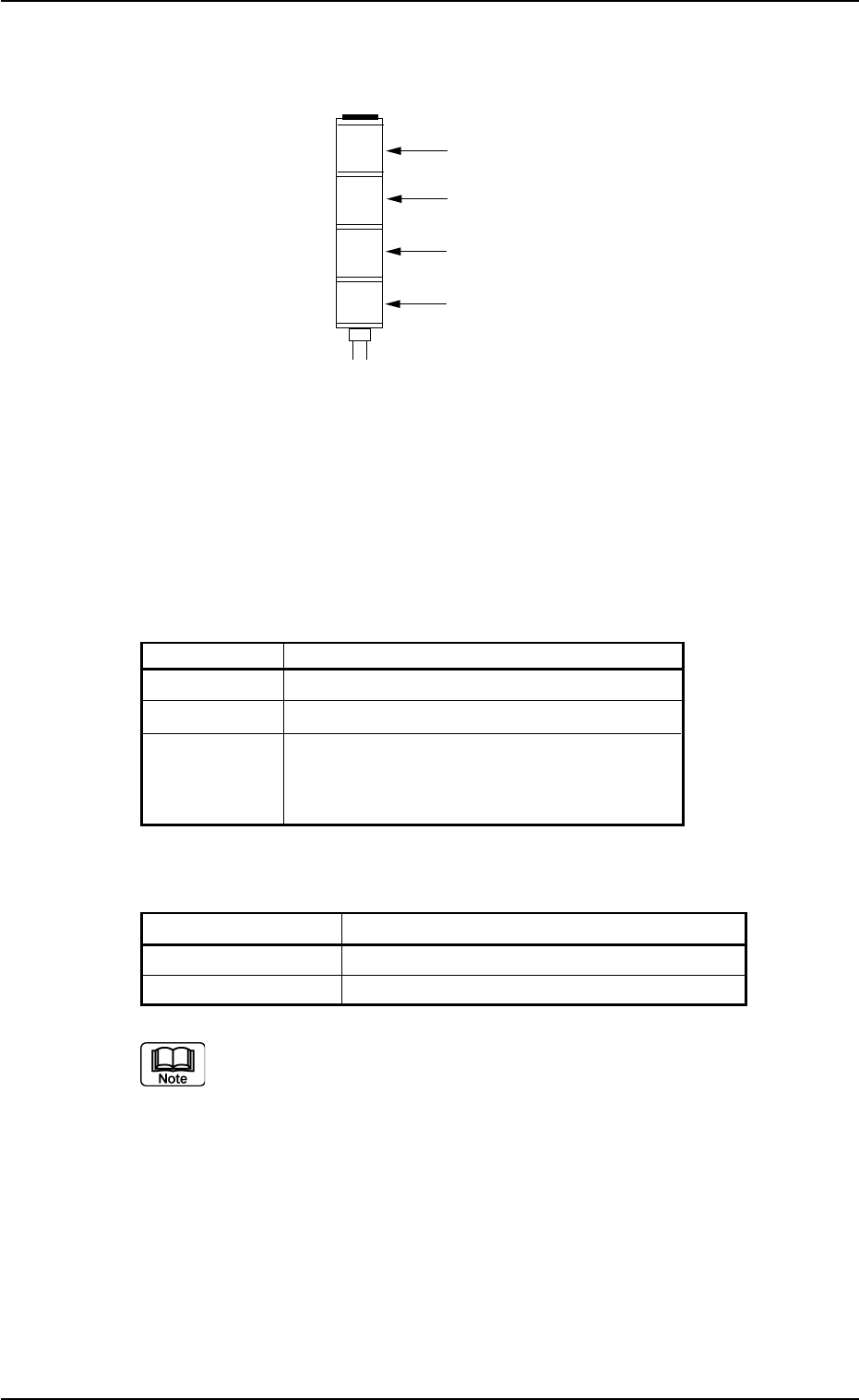
2.3.2 Light Tower
Fig. 1A10
The light tower indicates the condition of the machine with the lamps
and buzzer sounds.
Lamp Colors
The machine is factory-adjusted upon shipment.
Table 1A2
Lamp Colors Machine Condition
Red Error (Machine Stop)
Yellow Component Shortage (Warning)
Green Automatic Operation
Note: When the machine is in the standby
mode, this lamp flashes.
Buzzer
Table 1A2-1
Buzzer Machine Condition
Continuous Sound Emergency Stop
Intermittent Sound Error Occurrence
The condition of the machine corresponding to the parameters
specified for each lamp color and buzzer sound can be changed
in the "Configuration Setup" tab sheet.
Refer to "3.4 "Configuration Setup" Tab" in "Section 5" of "Vol. 3
Programming and Machine Data" for details.
2.3 Operational Measures
0207-003 1-11 AFO01EOPP
Red
Yellow
Green
Buzzer
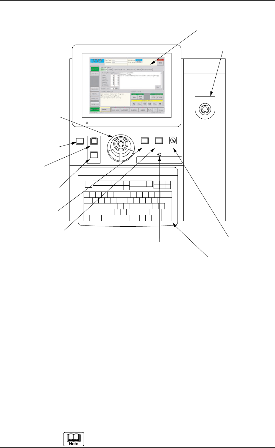
2.3.3 Front Operation Panel
Fig. 1A11
Arranged on the operation panel are switches and buttons required to
operate the machine.
The machine is provided with front and rear operation panels and can
be operated from either one of the panels. Panel selection is possible
with the [PNL CHANGE] buttons.
*1 [POWER ON] Button
• This button is used to turn on the power for operations.
*2 [START] Button
• This button is used to start the automatic operation.
The automatic operation can be started only when the lamp is flickering.
• While the lamp of this button is ON, it indicates that the machine is running
automatically.
When the [STOP] button is pressed during automatic operation, the lamp
extinguishes.
The lamp is kept ON while each device is being zeroed.
POWER ON
STOP
START
*1 [POWER ON] Button
*2 [START] Button
*3 [STOP] Button
*9 Keyboard
*8 [EMERGENCY STOP]
Switch
*7 [OPERATION] Switch
*5 [PNL CHANGE] Button
*4 [ENABLE] Button
*11 Front Touch Screen
*6 [LOCK] Lamp
*10 Pointing Device
EMERGENCY STOP
ENABLE
RUN SETUP
OPERATION
LOCK
PNL CHANGE
0307-005 1-12 AFO01EOPP
2.3 Operational Measures