1OM-1050-002.pdf - 第111页
(2) Press the [Origin/Signal Info.] tab to open the "Origin/Signal Info." tab sheet and perform the zeroing operations. Fig. 1C12 When the origin marks " • " are not displayed for all devices ex- cept…
This machine is provided with a password function which pre-
vents various types of data groups from being deleted by mis-
take and keeps unauthorized user (third party) from operating
the machine.
The following three kinds of passwords are available and each
gives individually approved user’s access to the computer sys-
tem of the machine.
Refer to "Password Setting" in "Section 5 Menus for System
Setting" of "Volume 3: Programming and Machine Data" for de-
tails.
[SUPERVISOR] : Access can be gained by only the person
identified as "Supervisor".
[OPERATOR #1] : Access can be gained by only the person
identified as "Operator #1". For example, the
person identified as "Operator #1" is given
a permission to all machine operations in-
cluding data editing.
[OPERATOR #2] : Access can be gained by only the person
identified as "Operator #2". For example, the
person identified as "Operator #2" is limited
to only the operations related to the auto-
matic operation.
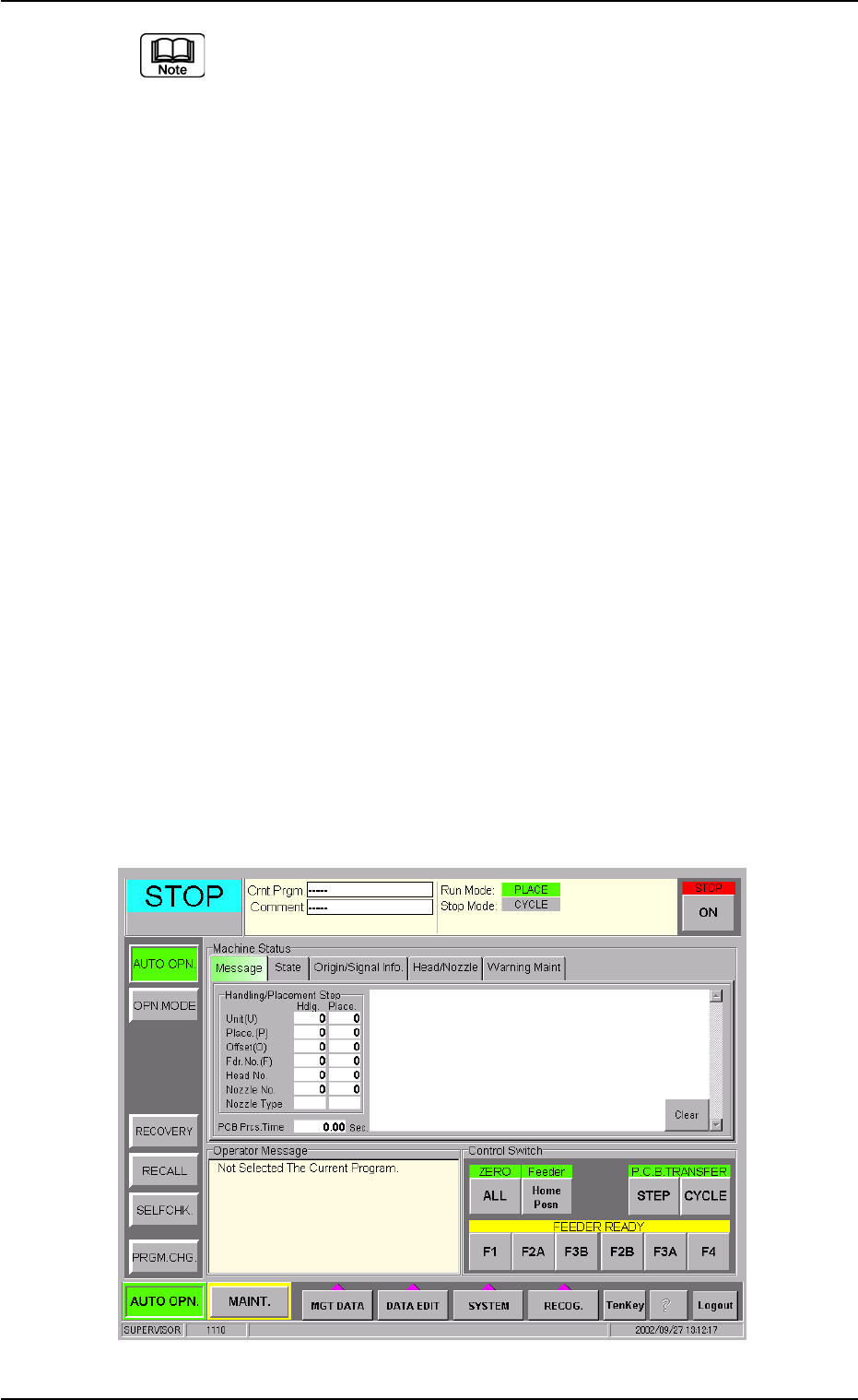
1.2.2 "AUTO OPN." Window and Zeroing of Each Device
(1) Enter the password and press the [Set] button.
The main menu bar appears and the "AUTO OPN." window opens
on the operation screen.
Fig. 1C11
0210-004 3 - 7 AFO01EOPP
1.2 Preparation before Automatic Operation
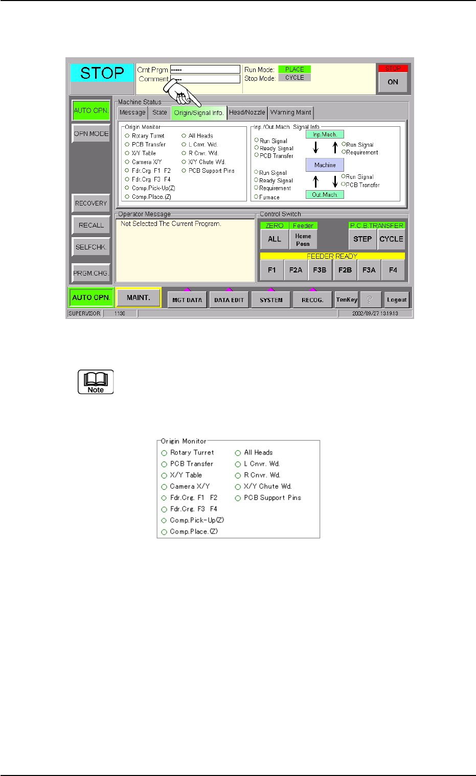
(2) Press the [Origin/Signal Info.] tab to open the "Origin/Signal Info."
tab sheet and perform the zeroing operations.
Fig. 1C12
When the origin marks "
•
" are not displayed for all devices ex-
cept "L Cnvr. Wd.", "R Cnvr. Wd.", "X/Y Chute Wd.", and "PCB
Support Pins" in the "Origin Monitor" group box of the "Origin/
Signal Info." tab sheet, the automatic operation cannot be started.
Fig. 1C13
When the origin mark "
•
" does not appear before any device other than
"L Cnvr. Wd.", "R Cnvr. Wd.", "X/Y Chute Wd.", and "PCB Support Pins",
follow the steps below to perform the zeroing operation.
Operation Procedure
1. Confirm that the machine is set in the "STOP" mode.
2. Confirm that the front safety door, the feeder work area safety doors,
and the feeder carriage covers are closed.
3. When the [ENABLE] button on the operation panel is pressed in two
seconds after the [ALL] button (entitled "ZERO"), all devices except
"L Cnvr. Wd.", "R Cnvr. Wd.", "X/Y Chute Wd.", and "PCB Support
Pins" are zeroed.
0210-005 3 - 8 AFO01EOPP
1.2 Preparation before Automatic Operation
1.2.3 Preparation for Components and P.C.B.’s
••
••
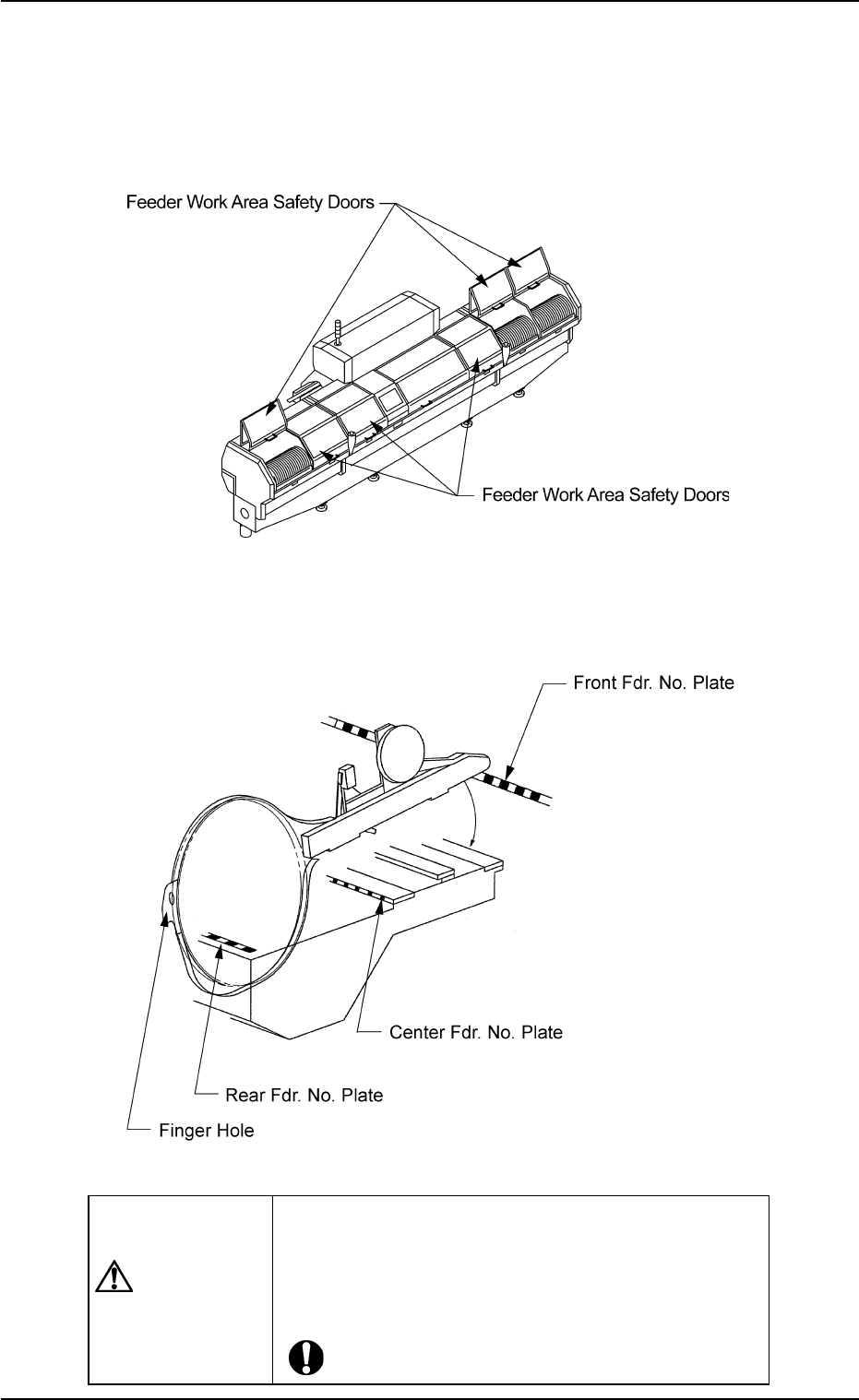
• Installation of Tape Feeders
(1) Open the feeder work area safety door of the feeder carriage
where the tape feeders should be installed.
Fig. 1C14
(2) Check which type of the tape feeder should be installed in which
slot No. (Fdr. No.). After that, install the tape feeders correctly.
Fig. 1C15
CAUTION
The tape feeders should be seated securely.
Otherwise, they may collide with the feeder installa-
tion error detection sensors or pick-up errors will oc-
cur.
0110-003 3 - 9
AFO01EOPP
1.2 Preparation before Automatic Operation