1OM-1050-002.pdf - 第56页
2.1.2 Rear Side of Machine Fig. 1A3 Rear Side of Machine 2.1 General View 01 10-003 1-3 AFO01EOPP
2. Name and Function of Each Section
2.1 General View
Refer to the items described in "2.2", "2.3", and "2.4" for each section.
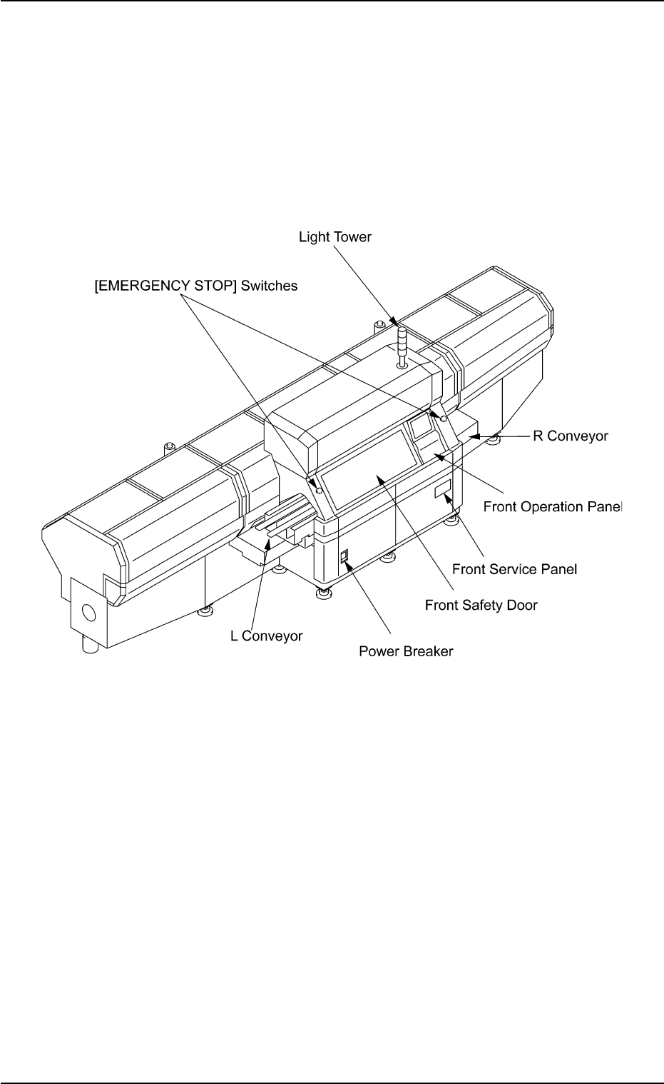
2.1.1 Front Side of Machine
Fig. 1A2 Front Side of Machine
2. Name and Function of Each Section
01 10-003 1-2 AFO01EOPP
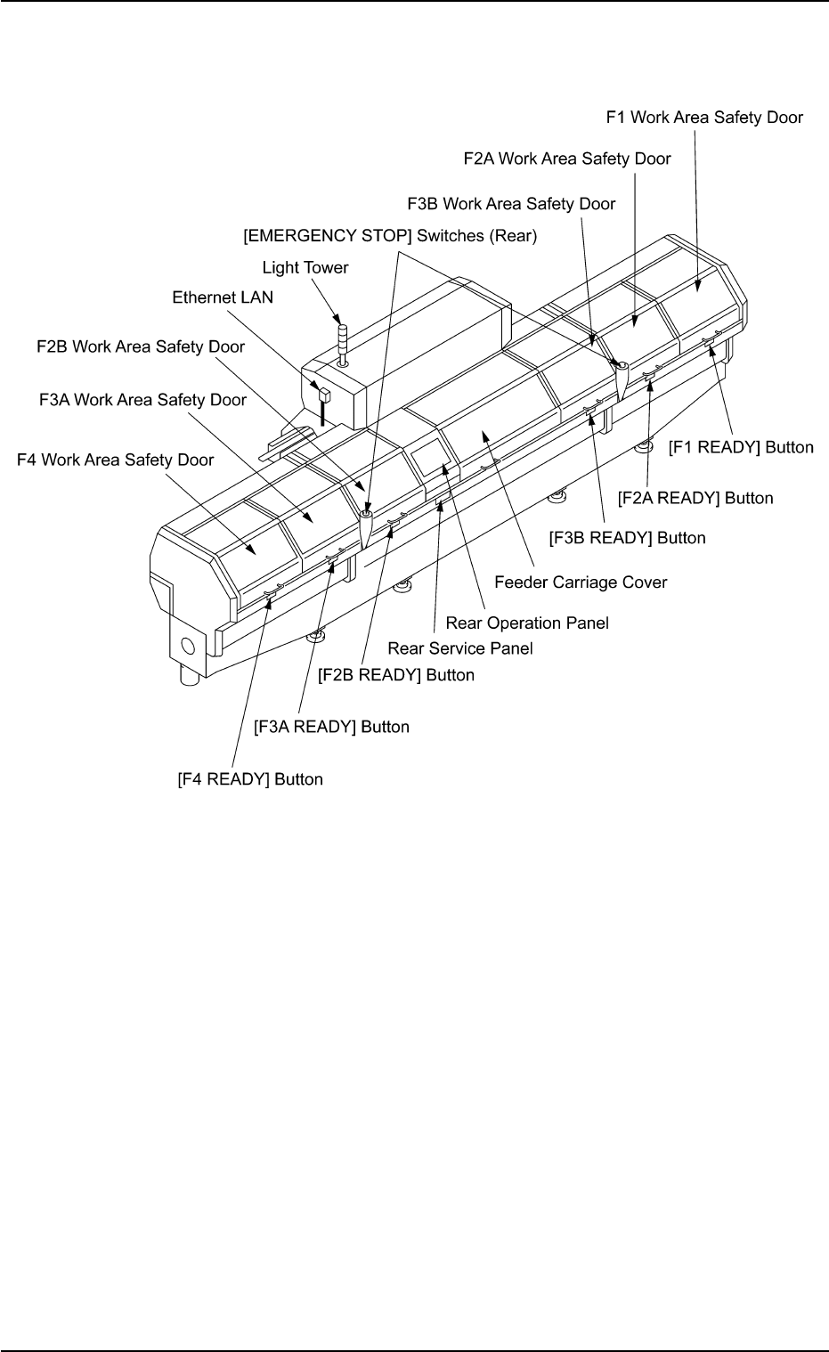
2.1.2 Rear Side of Machine
Fig. 1A3 Rear Side of Machine
2.1 General View
01 10-003 1-3 AFO01EOPP
2.2 Safety Devices
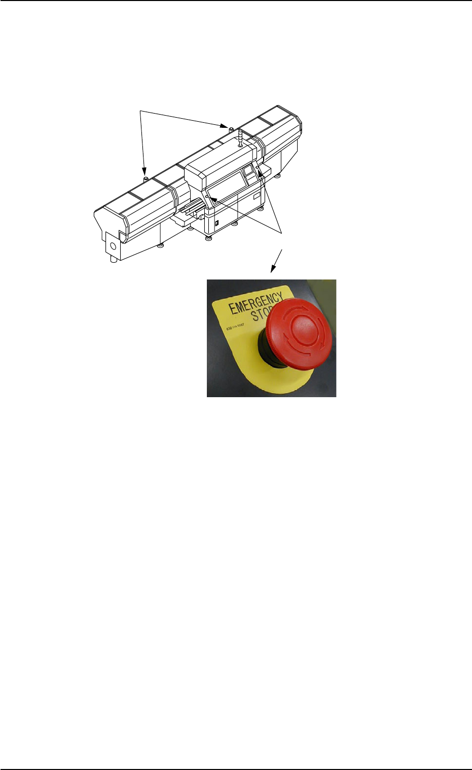
2.2.1 [EMERGENCY STOP] Switches
Fig. 1A4
Use the [EMERGENCY STOP] switches to immediately stop the ma-
chine in an emergency.
When an [EMERGENCY STOP] switch is pressed, the power is turned
off and the machine stops immediately.
When the power is turned off, the LED of the [POWER ON] button on
the operation panel illuminates in red.
••
••
• Locking the [EMERGENCY STOP] Switch
When an [EMERGENCY STOP] switch is pressed, all power is shut
off, the machine stops running, and the [EMERGENCY STOP] switch
is locked to avoid any careless power re-supply to the machine.
••
••
• Unlocking the [EMERGENCY STOP] Switch
Before re-supplying power to the machine, check and remove the
cause of emergency stop and inspect each section of the machine.
Then, unlock the [EMERGENCY STOP] switch.
To unlock the switch, turn the switch clockwise and pull it out.
2.2 Safety Devices
0307-005 1-4 AFO01EOPP
[EMERGENCY STOP] Switches (Front)
[EMERGENCY STOP] Switches (Rear)