00195193-02 SG D4 FSE en (1).pdf - 第102页
Communication and Control Reading the Board IDs out of the EEPROM Board type recognition Student Guide SIPLACE D4 (FSE) EN 09/2006 Communica tion and Control 101 Device number ID 02 vacuum gener ator analog 4.4 - 11: Dev…
Communication and Control
Board type recognition Reading the Board IDs out of the EEPROM
Student Guide SIPLACE D4 (FSE)
Communication and Control EN 09/2006
100
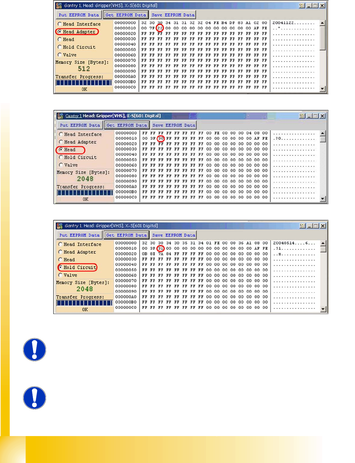
4.4 - 8: Head adapter board type recognition ID 22 for the C&P20 head
4.4 - 9: C&P20 board ID 30
4.4 - 10: C&P20 board ID 31 vacuum sensor, hold circuit
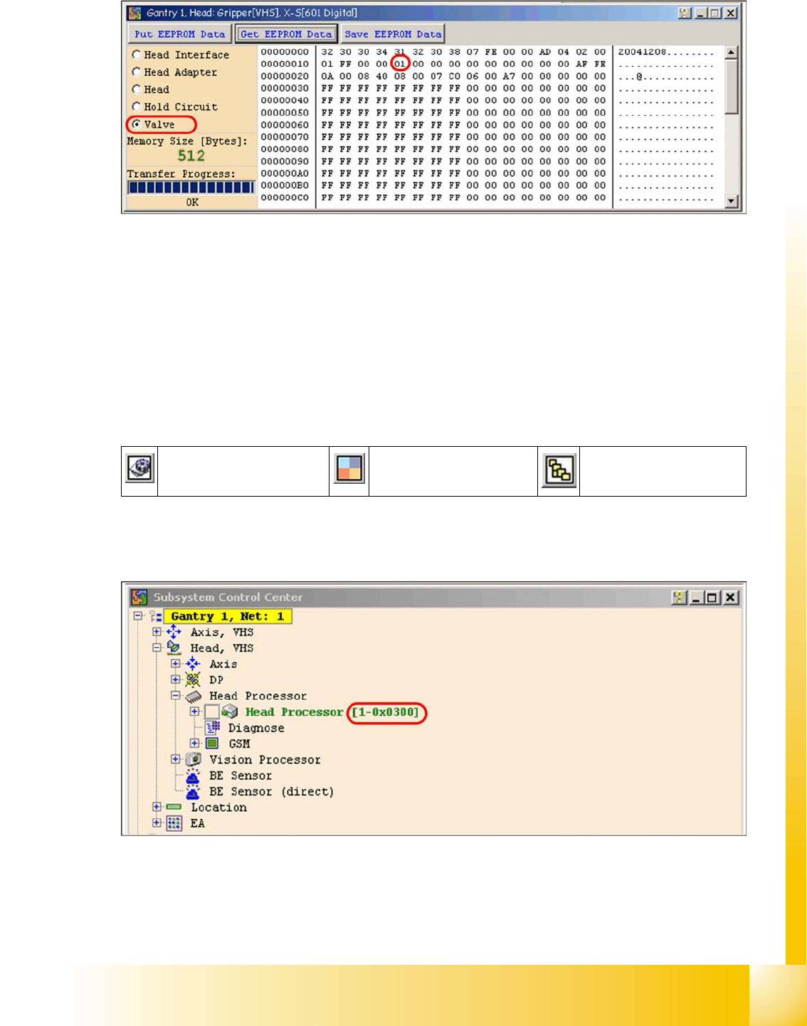
Device number ID 01 vacuum generator digital
NOTE:
The vacuum generator digital (C&P20) and thevacuum generator analog (Twin
head) don‘t have a board type ID. In the memory space on the EEPROM stays
00.
NOTE:
Both vacuum generators will be recognized via a device number. This
assembly ID is at storage location 14 in the EEPROM.
Communication and Control
Reading the Board IDs out of the EEPROM Board type recognition
Student Guide SIPLACE D4 (FSE)
EN 09/2006 Communication and Control
101
Device number ID 02 vacuum generator analog
4.4 - 11: Device number vacuum generator digital C&P20
4.4.2.2 Reading and Writing the Board IDs with CAN Commands
X Switch off the machine.
X Connect the service laptop to the machine CAN bus at PA1 and/or PA2.
Make sure that the cable to channel 1 is connected to PA 1 and that the transceiver is connected to
channel 2 of the Kvaser Card or switch off the query for the transceiver at channel 2 in the
Advanced
Subsystem Configuration
menu.
X Switch on the machine
X Start the
Caccia
software and check the machine configuration in
Caccia
.
X This can be opened by double-clicking on the
Subsystem control center
.
X Press on the
Get Versions
.
All available subsystems will be shown with their firmware versions and their CAN IDs.
4.4 - 12: Subsystem control center
X In the
Subsystem control center
window, search for the subsystem (TQM module), which you want
to access, in order to then use the correct CAN ID in the network window.
X That means, for check the Head interface, Head adapter and Intermediate distributor use the CAN
ID 300 for Gantry 1 or 308 for Gantry 2 and so on.
Subsystem control center Machine configuration
window
Advanced
Subsystem Configuration

Communication and Control
Board type recognition Reading the Board IDs out of the EEPROM
Student Guide SIPLACE D4 (FSE)
Communication and Control EN 09/2006
102
X To write the board IDs with CAN commands, make sure that just the BIOS is running on the TQM
module.
X Perform a BIOS download to the TQM module, so that you are sure that only the BIOS is running.
X Open the network 1 for PA 1 and network 2 to for PA 2.
X With the correct CAN ID and the BIOS commands, you can now write the correct board ID in the
EEPROM.
NOTE:
Always use the IDs which are shown in the subsystem control window, when
you click on the
GET VERSION or ACTIVATE IDs
button.
e.g. Head Processor
Gantry 1 -->
300
Gantry 2 -->
308
Gantry 3 -->
310
Gantry 4 -->
318
.
Exception: If you don‘t received a message from a subsystem, so you can try to
work with "Standard ID‘s" e.g.Head processor:
Gantry 1 -->
304
Gantry 2 -->
30c
Gantry 3 -->
314
Gantry 4 -->
31c
,
Required when two board IDs are missing.