00195193-02 SG D4 FSE en (1).pdf - 第274页
Modular conveyor Techni cal data Technical data - dual conveyor S tudent Guide SIPLACE D4 (FSE) Modular conveyor EN 09/2006 258 1 1.2.2 T echnical dat a - dual conveyor Fixed conveyor side Right (standard), left (optiona…

Modular conveyor
Technical data - single conveyor Technical data
Student Guide SIPLACE D4 (FSE)
EN 09/2006 Modular conveyor
257
11.2 Technical data
11.2.1 Technical data - single conveyor
Fixed conveyor side Right (standard), left (optional)
Max. component height 6 mm for the C&P12
PCB format (LxW) 50mm x 50 mm up to 368 mm x 460 mm
Long board up to 610 mm (24"), (option)
PCB thickness 0.3 mm to 4.5 mm
Max. PCB warpage upwards: 6 mm - board thickness
downwards: 0.3 mm + PCB thickness
Clearance on board underside max. 40 mm
PCB transport height 830 mm ±15 mm (Standard)
900mm ±15mm (Option)
930 mm±15 mm (Option)
950 mm ±15 mm (Option SMEMA)
Type of interface SMEMA (Standard)
SIEMENS (Option)
PCB weight 3 kg
Component-free PCB handling edge 3mm
PCB changeover time 2.5 s
Ink spot recognition possible
Automatic width adjustment possible

Modular conveyor
Technical data Technical data - dual conveyor
Student Guide SIPLACE D4 (FSE)
Modular conveyor EN 09/2006
258
11.2.2 Technical data - dual conveyor
Fixed conveyor side Right (standard), left (optional)
Max. component height 6 mm for the C&P12
PCB format(LxW) 50mm x 50 mm up to 368 mm x 216 mm
2" x 2" to 18" x 8.5"
Long board up to 610 mm (24"), (option)
PCB thickness 0.3 mm to 4.5 mm
Max. PCB warpage upwards: 6 mm - board thickness
downwards: 0.3 mm + PCB thickness
Clearance on board underside max. 40 mm
PCB transport height 830 mm ±15 mm (Standard)
900mm ±15mm (Option)
930 mm±15 mm (Option)
950 mm ±15 mm (Option SMEMA)
Type of interface SMEMA (Standard)
SIEMENS (Option)
PCB weight 3 kg
Component-free PCB handling edge 3mm
PCB changeover time 2.5 s
Conveyor mode synchronous or asynchronous
Components on each conveyor same or different
PCB width on each conveyor same or different
Ink spot recognition synchronous: not possible, asynchronous:
possible
Automatic width adjustment possible
Modular conveyor
Adjusting the Tension of the Conveyor Toothed Belt Conveyor Settings
Student Guide SIPLACE D4 (FSE)
EN 09/2006 Modular conveyor
259
11.3 Conveyor Settings
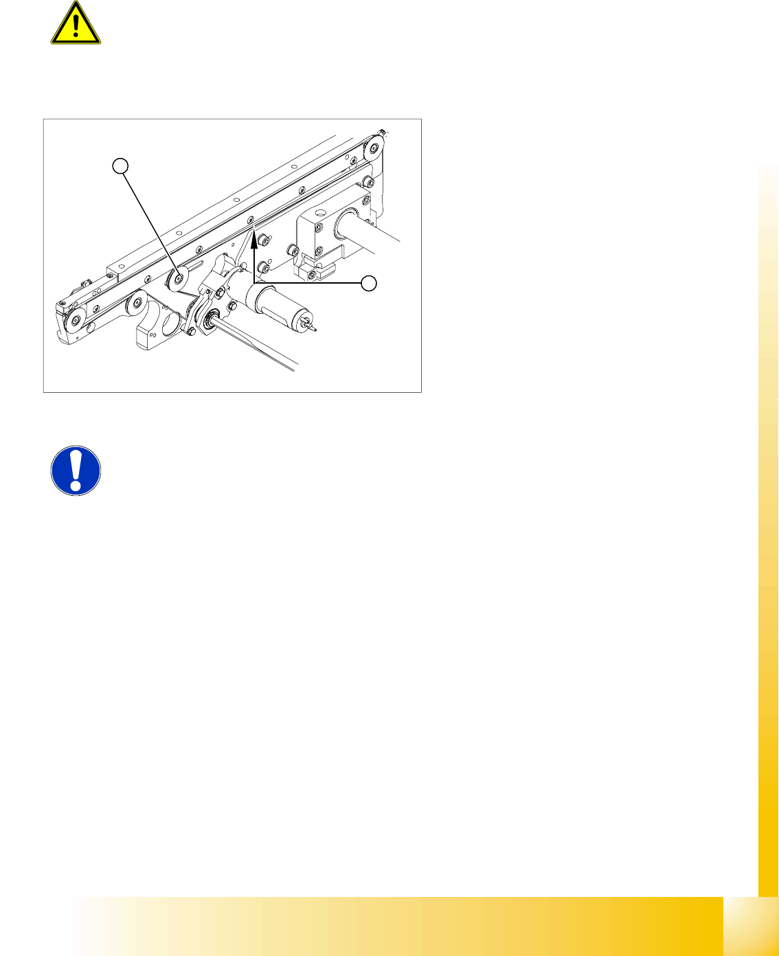
11.3.1 Adjusting the Tension of the Conveyor Toothed Belt
ATTENTION: Press the EMERGENCY STOP!
Before performing adjustment work you must ensure that the lifting table has
been secured against movement!
Legend:
1. Deflection pulley with slot
2. Measuring point of the belt tension measuring
device (strand center).
X The deflection pulleys, around which the
conveyor toothed belt is run at approximately
180°, are fastened at a slot. The tension of the
conveyor toothed belt can be adjusted by
moving this deflection pulley.
X Position the measuring point of the belt
tension device at the strand center (i.e. the
longest distance between the two deflection
pulleys) of the conveyor toothed belt.
X Adjust the belt tension according to the
following values.
1
2
NOTE:
The tension frequencies per area may vary according to the different belt
guides. The belt tension always remains the same.