00195193-02 SG D4 FSE en (1).pdf - 第48页
Overview General Overview of Assemblies Pneumatic Unit S tudent Guide SIPLACE D4 (FSE) Overview EN 09/2006 48 3.2.3 Pneumatic Unit The pneumatic unit is a fixed inst allation in side the machine and is located to th e ri…
Overview
Axis Unit and Computer Unit General Overview of Assemblies
Student Guide SIPLACE D4 (FSE)
EN 09/2006 Overview
47
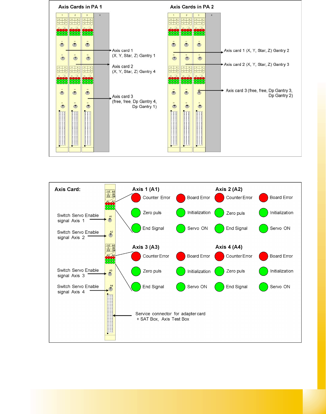
3.2.2.2.2 Axis controller boards
3.2 - 3: Axis controller boards
3.2.2.2.3 Axis board A364
3.2 - 4: D4 axis board
Overview
General Overview of Assemblies Pneumatic Unit
Student Guide SIPLACE D4 (FSE)
Overview EN 09/2006
48
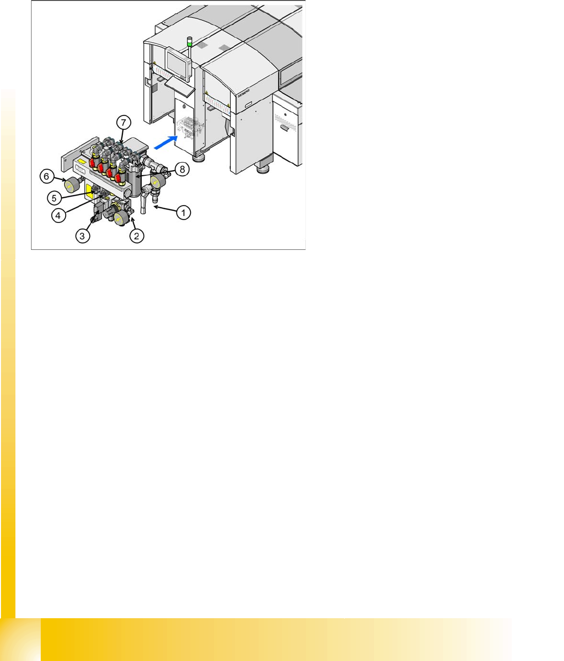
3.2.3 Pneumatic Unit
The pneumatic unit is a fixed installation inside the machine and is located to the right of the middle
section of the machine, behind a flap. The pneumatic unit includes all electrical connections for control/
regulation of the compressed air supply.
3.2.3.1 Compressed Air Distributor Block
The pneumatic unit is used to prepare and distribute the compressed air required in the machine. The
pressure at the compressed air connection must be at least 4.5 bar.
The following pneumatic circuits are supplied with compressed air via the distributor block:
Gantries 1 - 4 (placement heads), vacuum generation: min. 4.5 bar
Conveyor system: 4.5 bar
Tape cutter for locations 1 - 4: 4.5 bar
Nozzle changer for locations 1 - 4: 4.5 bar
Feed-in units for the changeover tables: 4.5 bar
Bulkcase feeder for locations 1 - 4: 2.5 bar
Fine adjustment for the individual pneumatic circuits is performed directly at the pneumatic units, via the
adjustment valves.
Legend
1. Main compressed air connection with shutoff
valve and manometer
2. 4x connection for bulkcase feeder with
manometer, adjustable (2.5 bar), location 1-4
3. 4x connection for cutters, location 1 - 4
(4.5 bar)
2x connection for conveyor lifting table
4. 4x Connection for nozzle changer (4.5 bar)
5. 4x connection for docking/undocking CO table
(4.5 bar)
6. Electronic control valve for incoming pressure
5.0 bar.
7. 4x connection for gantries 1 - 4, vacuum
generation C&P head with shutoff valves
8. Compressed air filter
Overview
Power Supply Unit General Overview of Assemblies
Student Guide SIPLACE D4 (FSE)
EN 09/2006 Overview
49
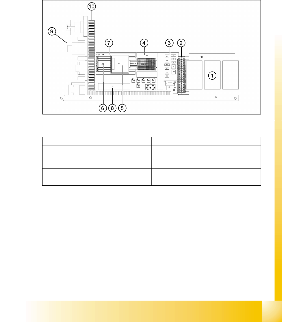
3.2.4 Power Supply Unit
The main power supply unit is mounted on a compact rack unit and is located on the left of the middle
section of the machine. From outside, you can only see the red main switch.
A lockable door prevents access to the power supply.
3.2.4.1 Overview of Voltages in the Power Supply Unit
3.2 - 5: Power supply – view of right-hand side
Legend
1 Transformer 1 6 Power supply A2 (5 V/6.3 A)
2 Secondary terminal strip with fuses (output
voltage T1)
7 Power supply A1 (24 V/40 A)
3 Connector strip X2-X10, X12, X13 8 Line filter Z1 (input voltage)
4 Terminal strip X1 9 Front view (see following diagram)
5 Power fail board A3 10 Inrush current limiter (behind the cable duct)