00195193-02 SG D4 FSE en (1).pdf - 第248页
Component handling Overview Student Guide SIPLACE D4 (FSE) EN 09/2006 Component handling 233 10 Component handling 10.1 Overview This chapter descr ibes the preparation of comp onents with the component changeo ver table…
C&P12 Placement Head
Nozzle changer Activation of Nozzle Changer at the C&P Head
Student Guide SIPLACE D4 (FSE)
C&P12 Placement Head EN 09/2006
232
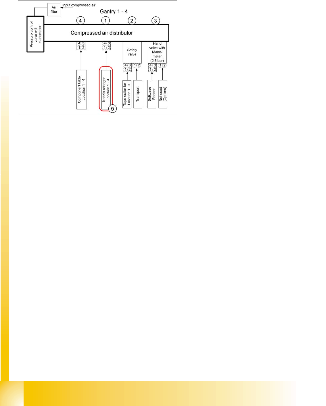
9.6.2 Activation of Nozzle Changer at the C&P Head
The nozzle changers are activated at the relevant
locations via the CAN Bus (SLIO main and sub
distributor). Solenoid valves activate the
pneumatic rotary drives to open or close the
nozzle changer.
Legend:
1 to 4: compressed air supply for vacuum
generator of C&P12 heads, gantries 1 to 4
5: Nozzle changer connections 1 - 4
Component handling
Overview
Student Guide SIPLACE D4 (FSE)
EN 09/2006 Component handling
233
10 Component handling
10.1 Overview
This chapter describes the preparation of components with the component changeover tables, the
corresponding docking unit and the pneumatic cutter.
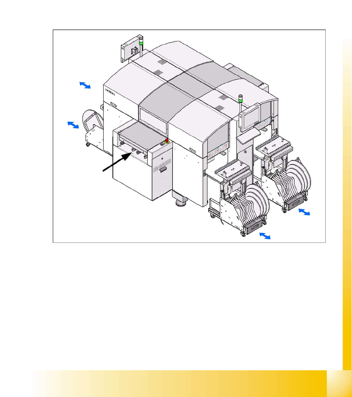
Up to four flexible CO tables can be docked onto the D4 machine. The CO changeover tables are
automatically connected to/disconnected from the docking unit at the press of a button. Plug-in electrical
and pneumatic connections link the machine to the CO changeover table.
10.1 - 1: Shows the buttons for docking and undocking the COT‘s
The table unit consists of the CO changeover table and the mechanics for raising and lowering the CO
table.
Component handling
Overview Technical Data component table:
Student Guide SIPLACE D4 (FSE)
Component handling EN 09/2006
234
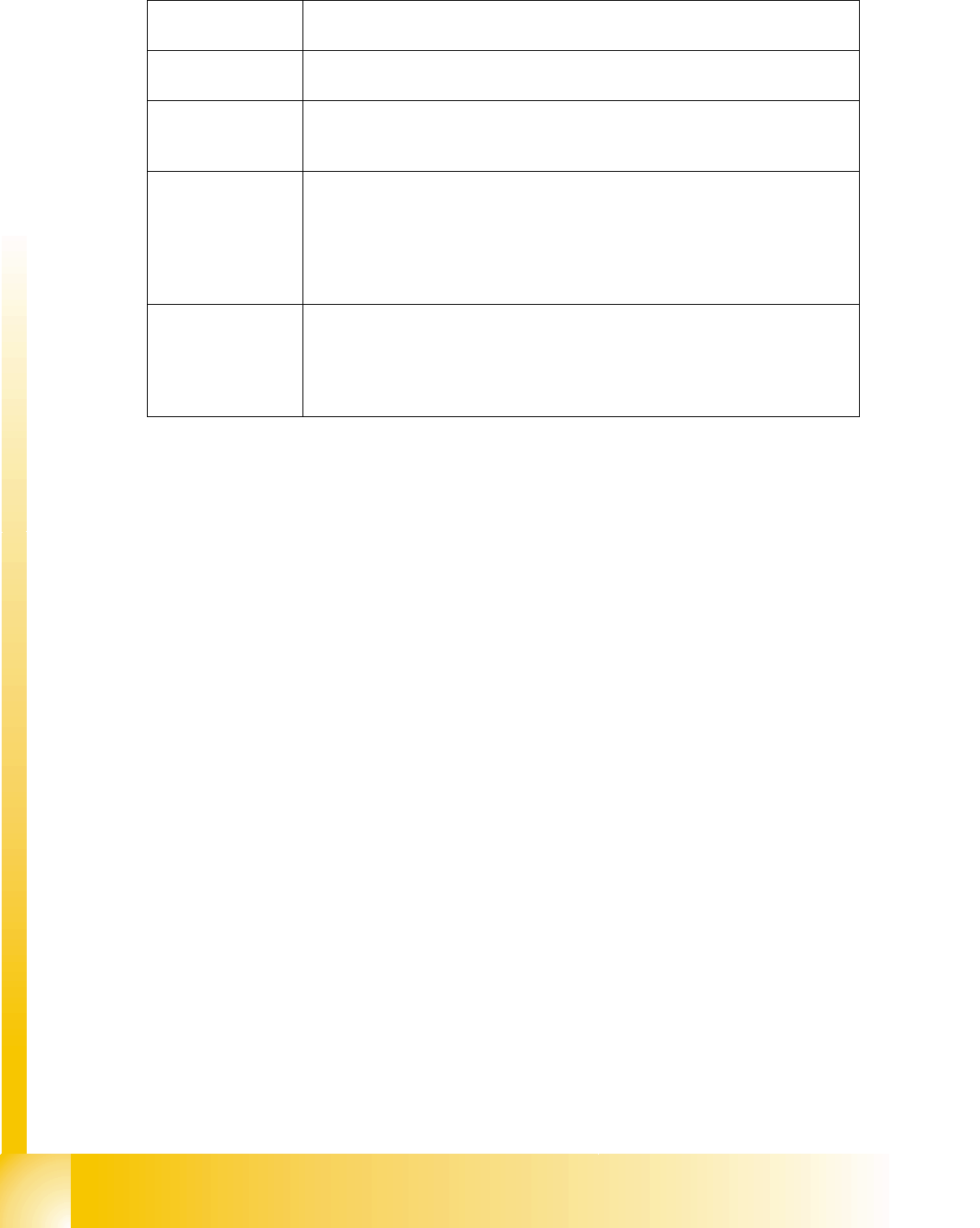
10.1.1 Technical Data component table:
Feeder capacity 144 tracks width 8mm (3x8mm S feeder)
96 tracks width 8mm (2x8mm S feeder)
Location 4 Component tables with the integrated tape waste container
12 tracks with 30 mm for each CO changeover table
undocking Tapes, Bulkcase, Linear magazin, Siplace S-Feeder(F4,F5,S-20,S-
23,S25HM,S27HM,HS50,HS50+,HS60), OEM Feeder, Surftape feeder (8, 12,
16, 24 mm), manual Trays
Interface to the
machine
Plug-in connection to machine
- Power supply
- CAN bus connection
- Closing the safety loop
- Compressed air connection
- Splice point recognition connection (optional)
Component table
height
depend from the machine height:
830 mm ± 15 mm (standard)
900 mm ± 15 mm (SMEMA)
930 mm ± 15 mm (SMEMA)
950 mm ± 15 mm (SMEMA)