00195193-02 SG D4 FSE en (1).pdf - 第233页
C&P12 Placement Head Travel Profiles - Placement Z-Axis Up S tudent Guide SIPLACE D4 (FSE) C&P12 Placement Head EN 09/2006 218 9.4.2.2 Placement: Z-Axis Up wards with "Slow St art" Benefits of Special M…
C&P12 Placement Head
Z-Axis Up Travel Profiles - Placement
Student Guide SIPLACE D4 (FSE)
EN 09/2006 C&P12 Placement Head
217
9.4.2 Z-Axis Up
9.4.2.1 Standard Mode - Placement: Z-Axis Up
LB down switches:
End position signal for downwards and valve
positioning drive "ON" for air kiss
Measurement of air kiss pressure during
placement
Start signal for upwards movement
Z-axis starts:
Positioning of Z-axis upwards
LB up switches:
Electromagnetic valve for air kiss OFF
Reset LB down signal
Start signal for gantry axes
Z-axis end position signal (Z-axis at 0 position):
Enables vacuum query: "Segment airtight"
after placement (SR/MC503)
Start signal for star axis
C&P12 Placement Head
Travel Profiles - Placement Z-Axis Up
Student Guide SIPLACE D4 (FSE)
C&P12 Placement Head EN 09/2006
218
9.4.2.2 Placement: Z-Axis Upwards with "Slow Start"
Benefits of Special Mode "Slow Start"
The CO stays on the board even if the soldering paste has a low holding force.
From LRU/LRL 503 and SIPLACE Pro, this
placement type can "only" be programmed in the
CS "for SR/MC 503 stations and higher".
LB down switches:
End position signal for downwards and valve
positioning drive ON for air kiss
Measurement of air kiss pressure during
placement
Start signal for upwards movement
Z-axis starts:
Positioning Z-axis up with reduced starting
speed for the first 44 digits
LB up switches:
Electromagnetic valve for air kiss OFF
Reset LB down signal
Start signal for gantry axes
Z-axis end position signal (Z-axis at 0 position):
Enables vacuum query: "segment airtight?"
after placement (SR/MC503)
Start signal for star axis
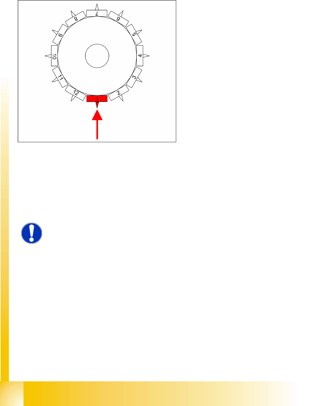
NOTE:
However, this option makes the placement procedure around 20 ms longer than
the standard placement procedure.
C&P12 Placement Head
Boards at C&P12 Settings
Student Guide SIPLACE D4 (FSE)
EN 09/2006 C&P12 Placement Head
219
9.5 Settings
9.5.1 Boards at C&P12
All the settings described in this chapter are head-specific and apply here for the C&P12.
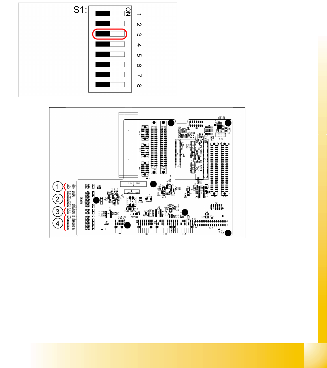
9.5.1.1 Switch S1 on the 8-fold DIP Switch of the Gantry Head Distributor – C&P12
9.5 - 1: LEDs on gantry head distributor
Legend
1. CAN signal
2. Power Supply Unit
3. Head Processor
4. LEDs C&P12
Legend:
S1 – Switch 3:
ON – Test mode (without delay)
OFF – Default state (with delay of 3.6 ms+/-
300 us) means: Z-axis moves downwards, the
top LB is released and the LB down is enabled
after a delay of 3.6 ms.