00195193-02 SG D4 FSE en (1).pdf - 第83页
Communication and Control CAN Bus CAN Bus Processor Board C&P Head S tudent Guide SIPLACE D4 (FSE) Communication and Control EN 09/2006 82 4.3.4 CAN Bus Process or Board C&P Head The TQM 167LC CAN bu s processor …
Communication and Control
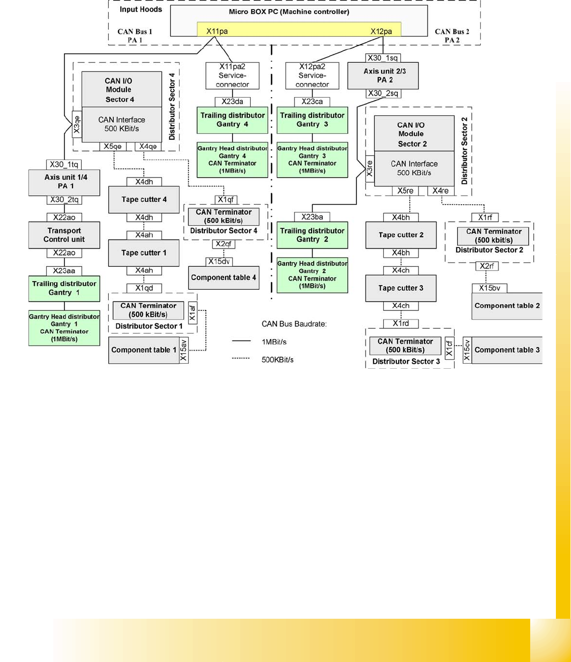
CAN Bus Structure SIPLACE D4 CAN Bus
Student Guide SIPLACE D4 (FSE)
EN 09/2006 Communication and Control
81
4.3.3 CAN Bus Structure SIPLACE D4
The SIPLACE D4 placement machine uses a bus system with a data transmission rate of 1 MBit/s. The
bus system begins at the communication board and is split in 2 paths. Each path ends with a120 Ohm
terminating resistor at the head board of the respective placement head.
The cutter and the CO table operate with 500 KBit/s , as does the HS60.
4.3 - 9: Overview of CAN bus structure for SIPLACE D4
SMP = Small Micro Processor
Communication and Control
CAN Bus CAN Bus Processor Board C&P Head
Student Guide SIPLACE D4 (FSE)
Communication and Control EN 09/2006
82
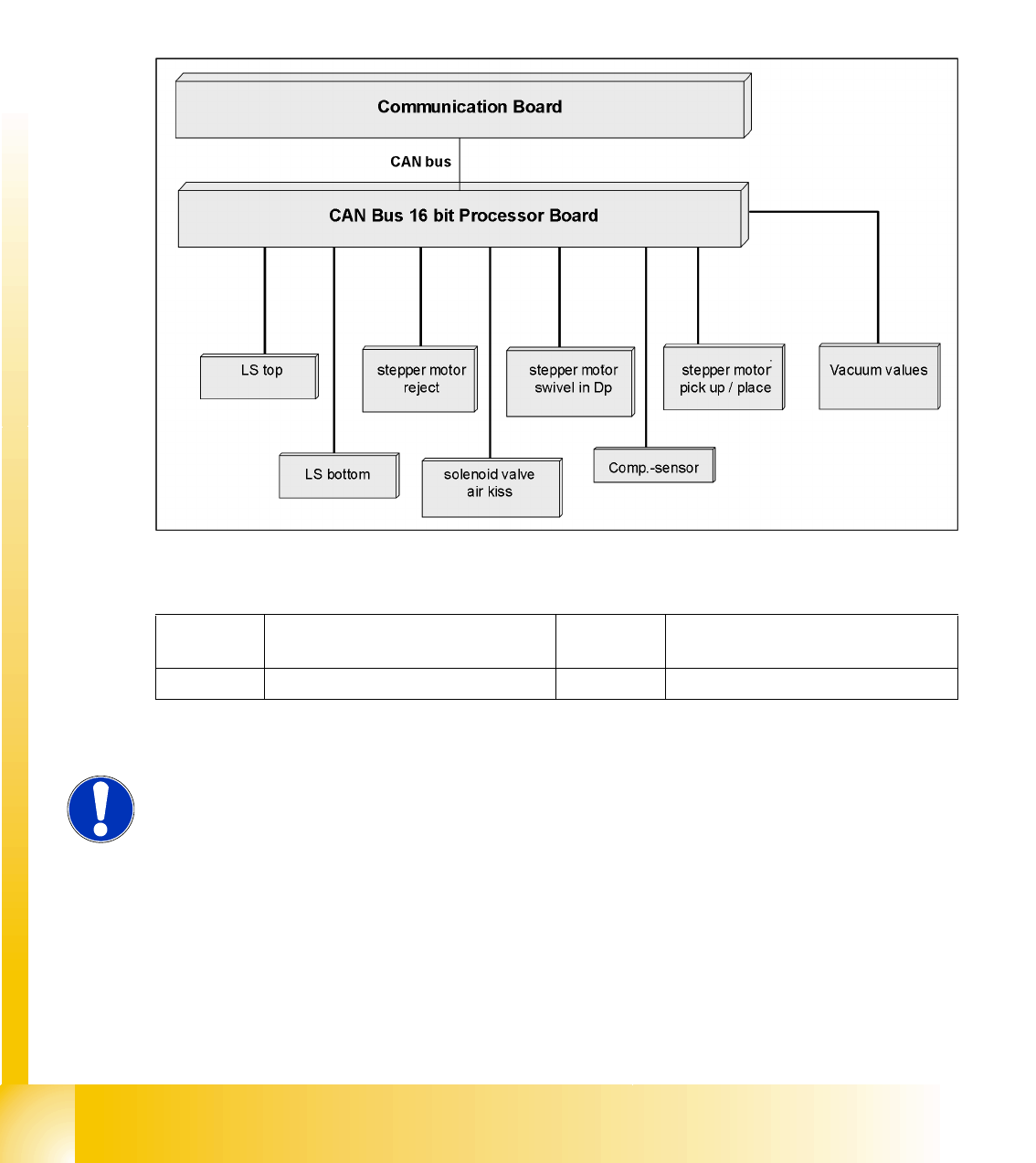
4.3.4 CAN Bus Processor Board C&P Head
The TQM 167LC CAN bus processor board is connected to the head board. The processor board is used
at different places in the machine. If the processor board on the head board, the firmware provides at
the processor board the control of the head specific actuators and sensors no matter which head type is
installed.
4.3.4.1 CAN BUS-Controlled Functions on the C&P12 Head
The following overview shows various head functions, controlled by the CAN system. Thus, the CAN bus
controls the actuators and sensors of the C&P head.
4.3 - 10: CAN function on C&P head
Legend
LB Light barrier Component
sensor
Component sensor
SM Stepping motor
NOTE:
The status of the 16 Bit PROCESSOR BOARD is indicated on the 7-segment
display.
Normal status on the display is: Display shows slowly flashed " . (for
description see Section C&P12).
Communication and Control
CAN Bus Terminator CAN Bus
Student Guide SIPLACE D4 (FSE)
EN 09/2006 Communication and Control
83
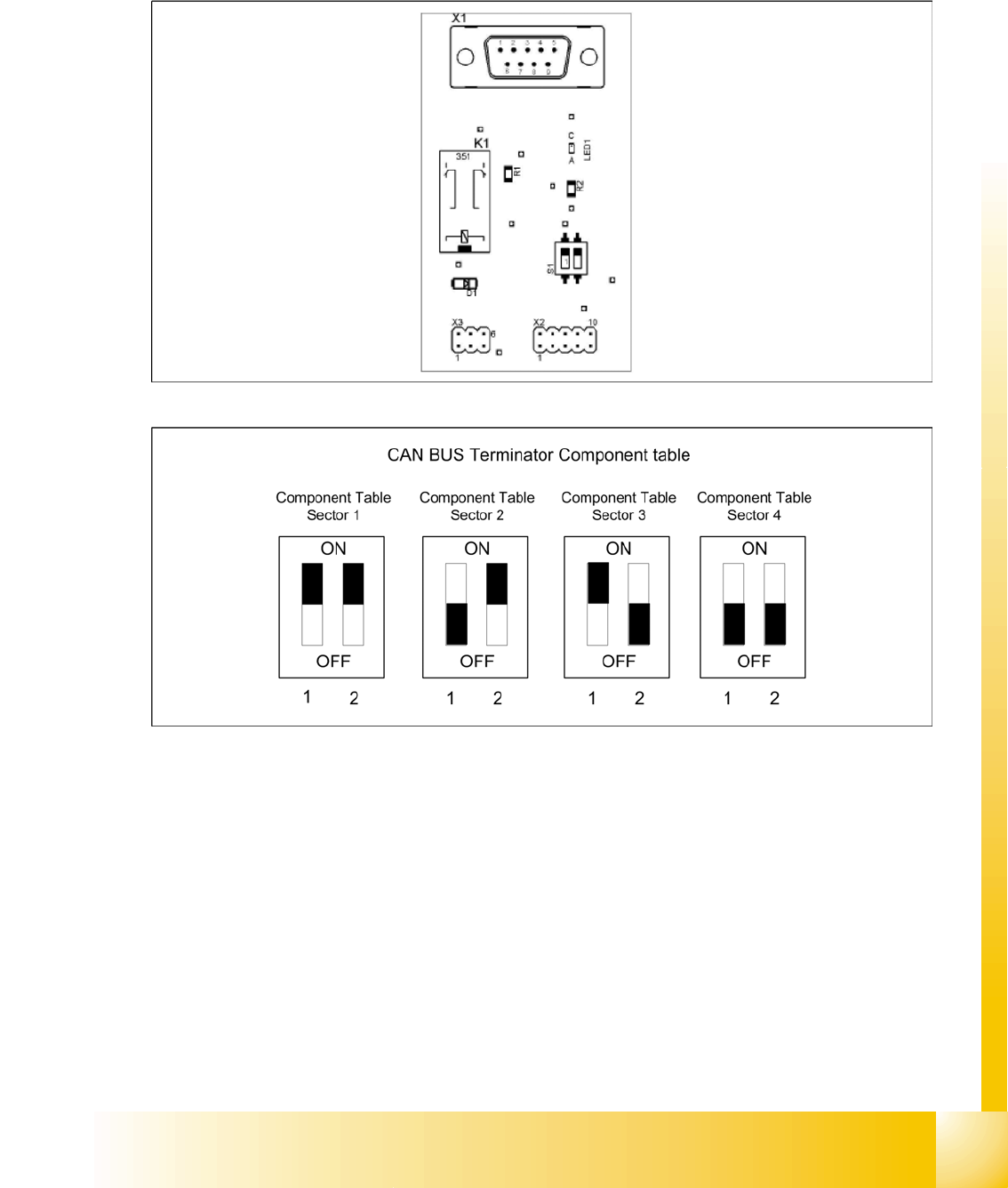
4.3.5 CAN Bus Terminator
The A3 assembly ensures that the CAN bus also functions with undocked CO tables. During undocking,
a CAN terminating resistor is switched, which maintains the CAN bus function and communication.
There is an A3 assembly in each sector.
4.3 - 11: A3 assembly
4.3 - 12: Switch S1 on A3