00195193-02 SG D4 FSE en (1).pdf - 第186页
Axis dynamic Axis control Dp-Axis Axis control C&P head axes Student Guide SIPLACE D4 (FSE) EN 09/2006 Axis dynamic 173 C&P-Head - signal for DP-axis, 3600 digits Legend: 1. Current signal: 200mV/Div 2. Control s…
Axis dynamic
Axis control C&P head axes Axis control Dp-Axis
Student Guide SIPLACE D4 (FSE)
Axis dynamic EN 09/2006
172
7.5.5.1 Check the dynamic DP-Axis
7.5.5.1.6 Test set up
SITEST:
X Select
C&P heads
==>
Select head
==>
Axis functions
==> Select the DP axis ==>
Axis dynamics
.
12segment C&P head DLM2 (angle resolution 0,025 degree):
X ==> "Select distance": 100 digits (2.5° rotation), and 3600 digits (90° rotation)
7.5.5.1.7 Example for dynamic with the control signal of the Vnom. output
The positioning by 100 digits equals 2.5 degrees and approx. 13 ms (see Section 7.5.5.1.7 Example for
dynamic with the control signal of the Vnom. output [J 171]). DP 12-segment head 90 degrees
(3600 digits) 39 +/-3 ms.
NOTE:
The measurement procedure is prepared and performed identically to that for
the star axis.
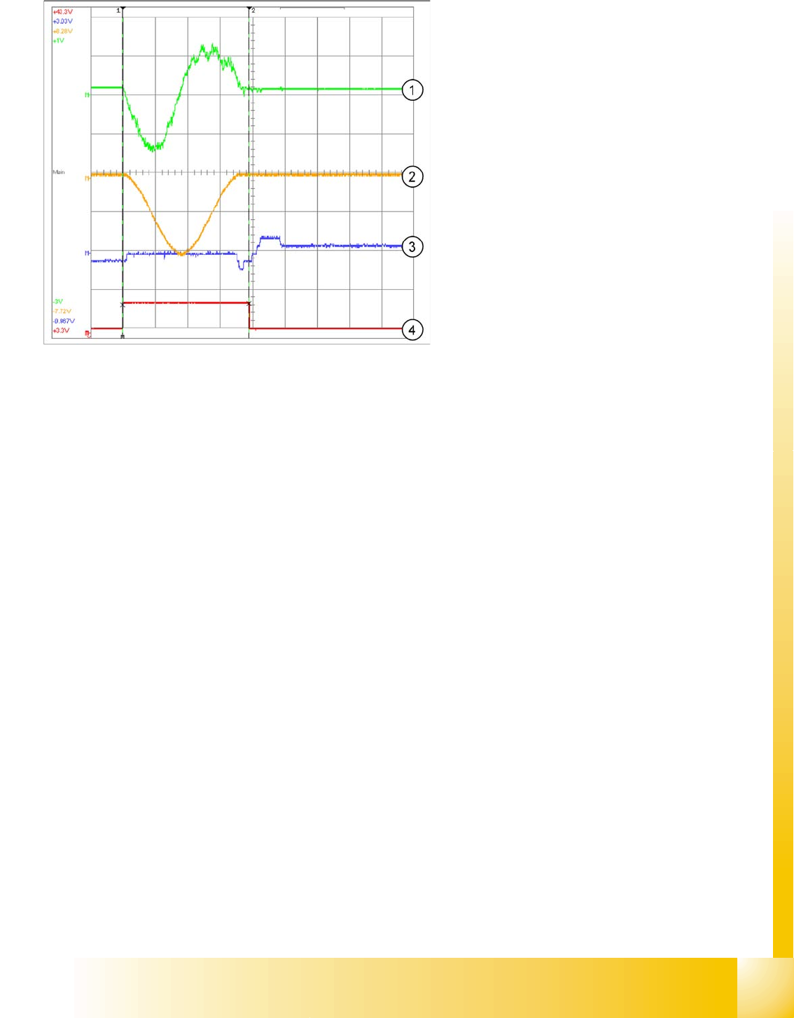
C&P-Head - signal for DP-axis, 100 digits
Legend:
1. Current signal for axis adapter
2. Motor current signal (at V nom. output) current
target value: 200mV/Div
3. Deviation of position 500mV/Div
4. End signal
Time basis: 5ms/Div
Positioning time: 13ms +/-3ms
Path: 100 digits
Axis dynamic
Axis control Dp-Axis Axis control C&P head axes
Student Guide SIPLACE D4 (FSE)
EN 09/2006 Axis dynamic
173
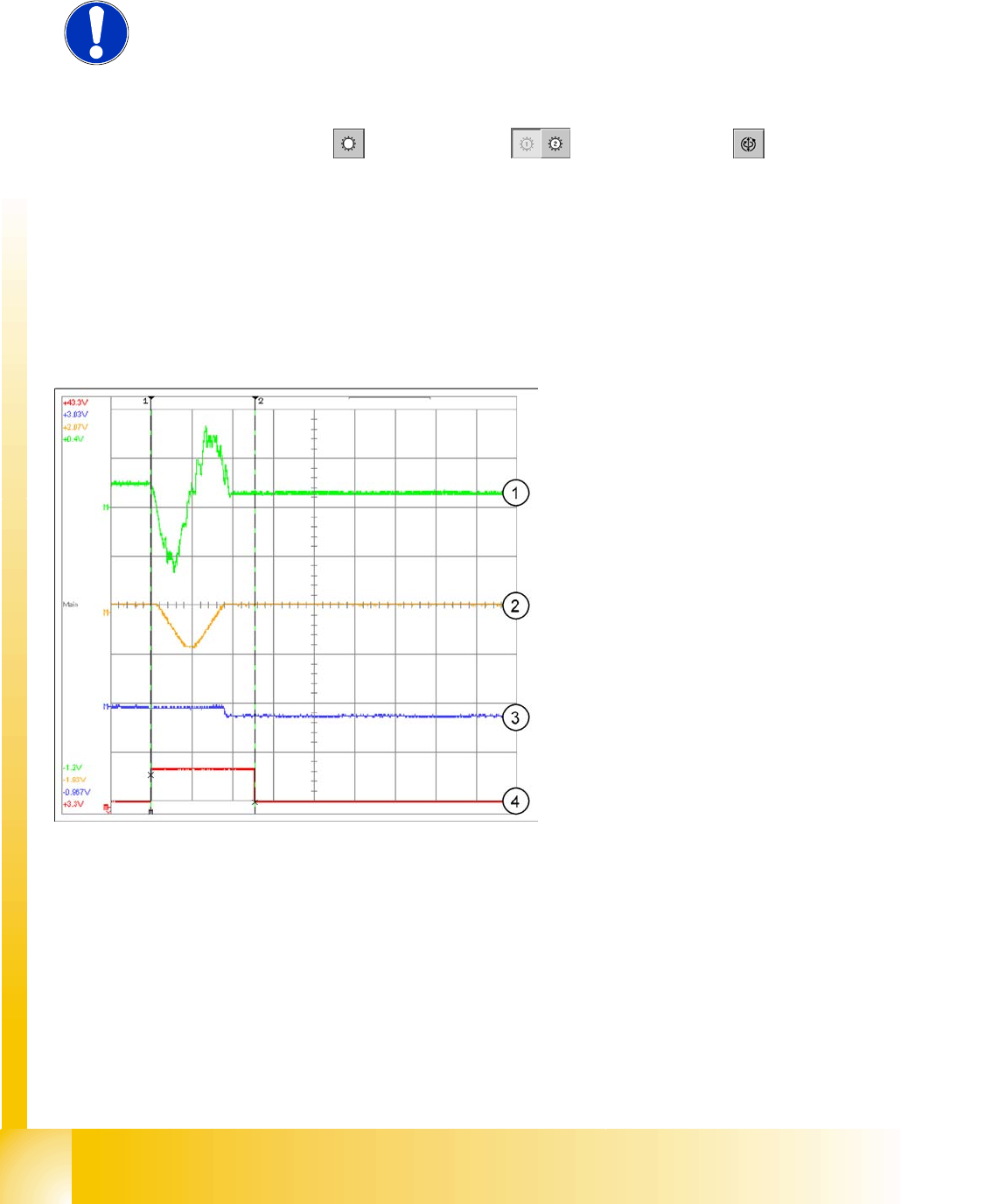
C&P-Head - signal for DP-axis, 3600 digits
Legend:
1. Current signal: 200mV/Div
2. Control signal Vnom.
3. Deviation of position 500mV/Div
4. End signal
Time basis: 10ms/Div
Positioning time: approx. 46 ms +/-3 ms
Path: 3600 digits
Gantry
Overview
Student Guide SIPLACE D4 (FSE)
EN 09/2006 Gantry
173
8Gantry
8.1 Overview
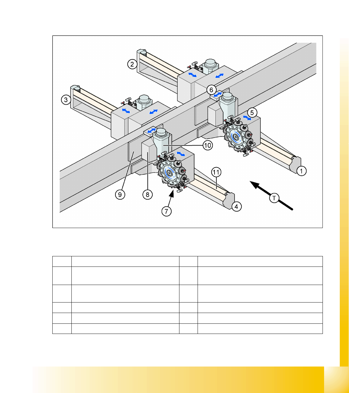
The gantries of the SIPLACE D machines each consist of an X and a Y axis. The Y-axis is driven by a
linear motor with integrated temperature sensor. The X axis is driven by a three-phase servo motor,
equipped with an integrated temperature sensor, and a belt. When viewed from the direction of transport,
the Y motors move from the right to the left side in positive counting direction and the X motors move
from the input conveyor to the output conveyer in positive counting direction. The placement heads are
mounted on the head plates of the respective X axis.
8.1 - 1: Position of gantries in D4 machines
Legend
1 Gantry 1 in placement area 1 7 PCB camera under the X-axis (here: gantry 4)
2 Gantry 2 in placement area 2 8 Y-motor, primary part – linear motor
(here: gantry 4)
3 Gantry 3 in placement area 2 9 Y-motor, secondary part – magnets
(here: gantry 4)
4 Gantry 4 in placement area 1 10 X motor (here: gantry 4)
5 X-axis (here: gantry 1) 11 Belt for X motor (here: gantry 4)
6 Y-axis (here: gantry 1) T Transport direction