00195193-02 SG D4 FSE en (1).pdf - 第114页
Reference run Initialization of the Stepper Motors Reference Run C&P12 Student Guide SIPLACE D4 (FSE) EN 09/2006 Reference run 107 5.3.2 Initialization of the Stepper Motors 5.3.2.1 Initialization of V alve Positioni…
Reference run
Reference Run C&P12 Overview Head Reference Run
Student Guide SIPLACE D4 (FSE)
Reference run EN 09/2006
106
5.3 Reference Run C&P12
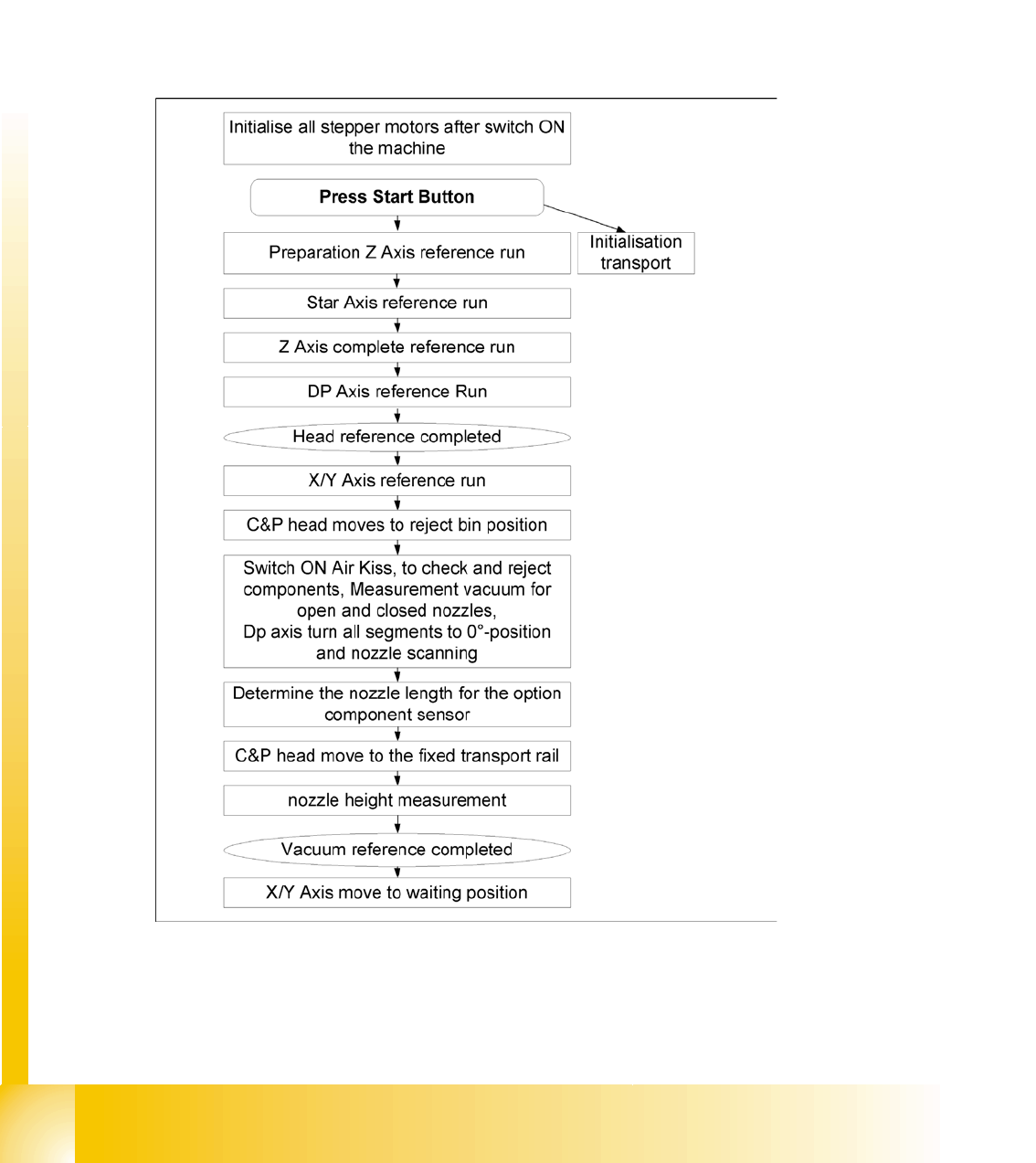
General procedure
The reference run procedure is identical to that for C&P12 type DLM3.
The reference run starts with the initialisation of all the head stepper motors. This allows then, the
head axis to reference by moving first to their zero pulses and then to their zero point correction
values.
In SIPLACE D4 machines, all heads and gantries move into the reference position at the same time.
5.3.1 Overview Head Reference Run
5.3 - 1: General reference run in detail
Reference run
Initialization of the Stepper Motors Reference Run C&P12
Student Guide SIPLACE D4 (FSE)
EN 09/2006 Reference run
107
5.3.2 Initialization of the Stepper Motors
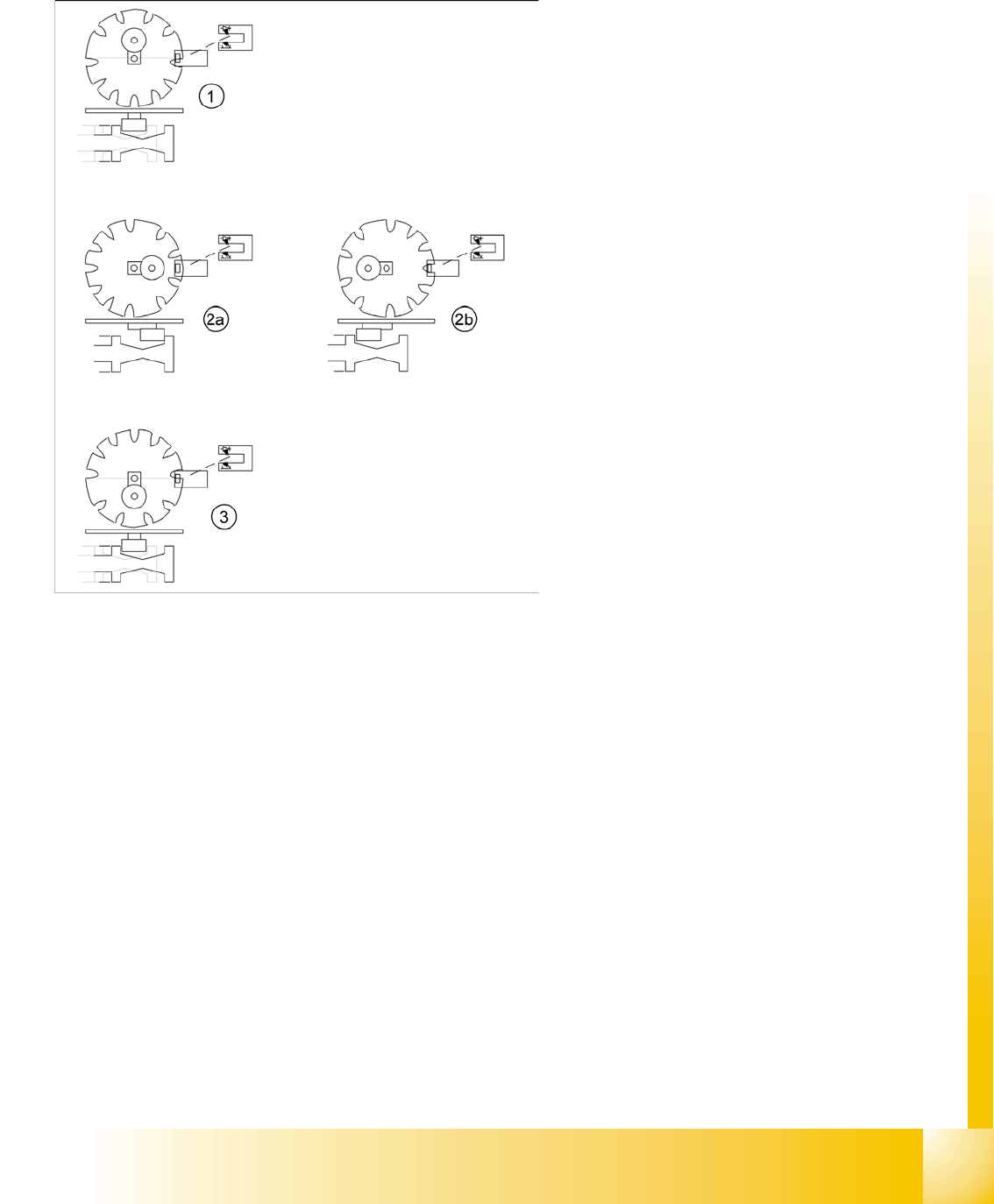
5.3.2.1 Initialization of Valve Positioning Drives for Pickup/Placement and Reject Positions
The stepping motor is used to move the plunger
(with eccentric movement), which then switches
on the vacuum supply and enables the component
to be picked up. During CO placement, the plunger
is triggered again to close the nozzle, so that air
kiss can be switched through to the nozzle for CO
placement. At CO release, the plunger switches
the air kiss on and the CO is released. After CO
release, the vacuum is switched back on again.
Legend:
1. Home position, initial position. Give way free
for Star axis movement. Drawing show 2
possible positions of the plunger
2. 2a: switches on vacuum, vacuum value
"Nozzle Open "
2b: switches on air kiss, vacuum value "Nozzle
Closed "
3. Counter position to initial position. Give way
free for Star axis movement.
– The stepper motor of the valve drive is
turned to the home position. The stepper
motor runs and the light barrier on the cam
disk sets the end signal.
– Because of the special shape of the cam
disk the stepper motor is able to recognize
the home position.
Reference run
Reference Run C&P12 Initialization of the Stepper Motors
Student Guide SIPLACE D4 (FSE)
Reference run EN 09/2006
108
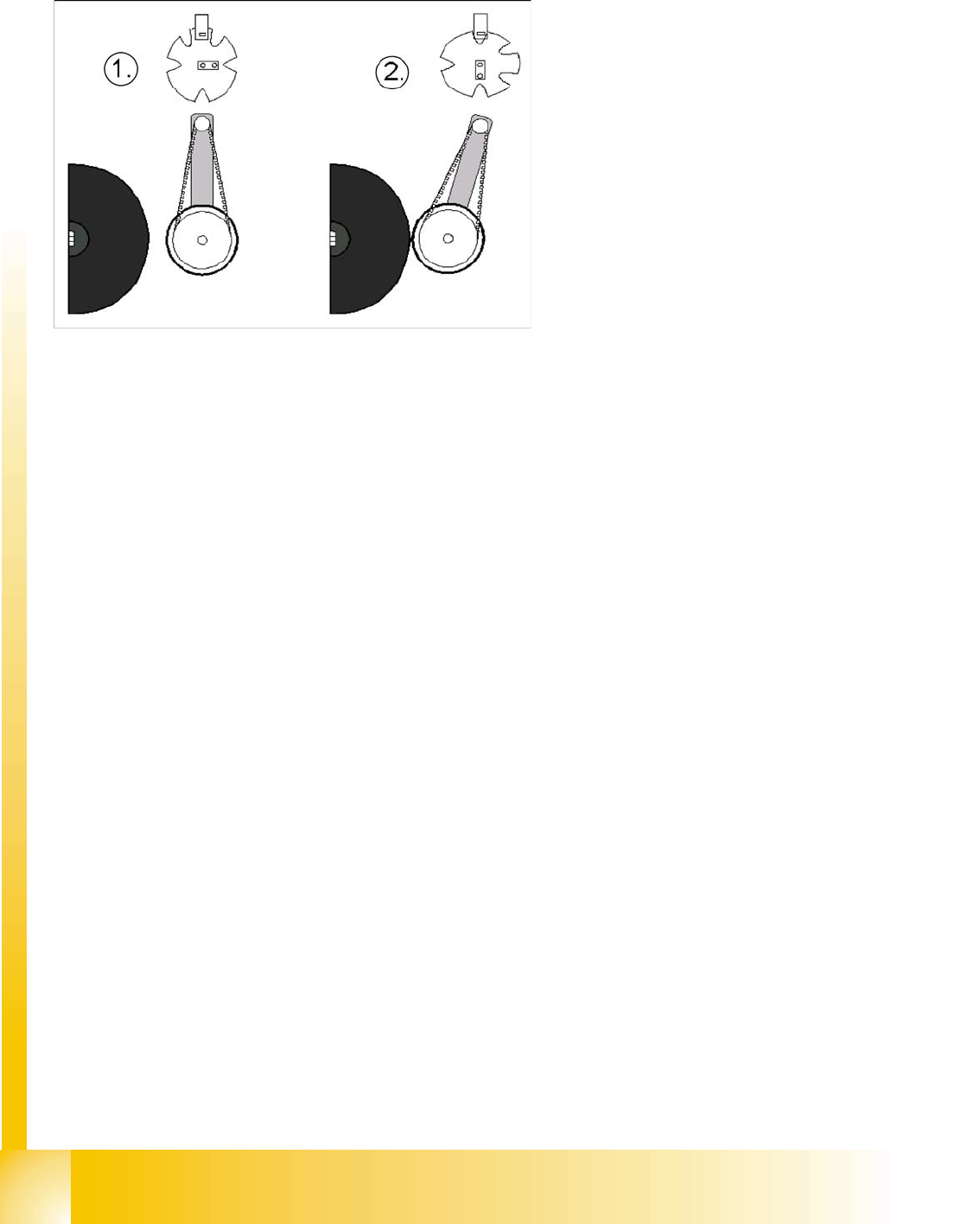
5.3.2.2 Initialize Valve Drive at DP-station
At the DP station, the stepping motor is used to
approach the sleeves (eccentric movement) and
rotate the CO/nozzles into the correct position, via
the DP axis.
Legend:
1. Home position DP drive around 1 mm away
from segment
2. Engaged position DP drive at segment
The stepper motor of the valve drive is turned
to the home position. The stepper motor runs
and the light barrier on the cam disk sets the
end signal.
Because of the special shape of the cam disk
the stepper motor is able to recognize the
home position.