00195193-02 SG D4 FSE en (1).pdf - 第154页
Axis dynamic Zero pulse at the position encoder Position measuring system Student Guide SIPLACE D4 (FSE) EN 09/2006 Axis dynamic 141 7.1.2 Zero pulse at th e po sition encoder Each incremental encoder system nee ds initi…
Axis dynamic
Position measuring system Track signals and Zero pulse signal
Student Guide SIPLACE D4 (FSE)
Axis dynamic EN 09/2006
140
The position is determined by a position counter on the axis controller. The moving direction of the axis
is determined by the phase shift of the track signals An advanced track A signal indicates movement to
the right, while an advanced track B signal indicates movement to the left. To make the encoder system
robust for the high resolution we multiply the frequency of the analoge signal and create a high resolution
digital measuring system.
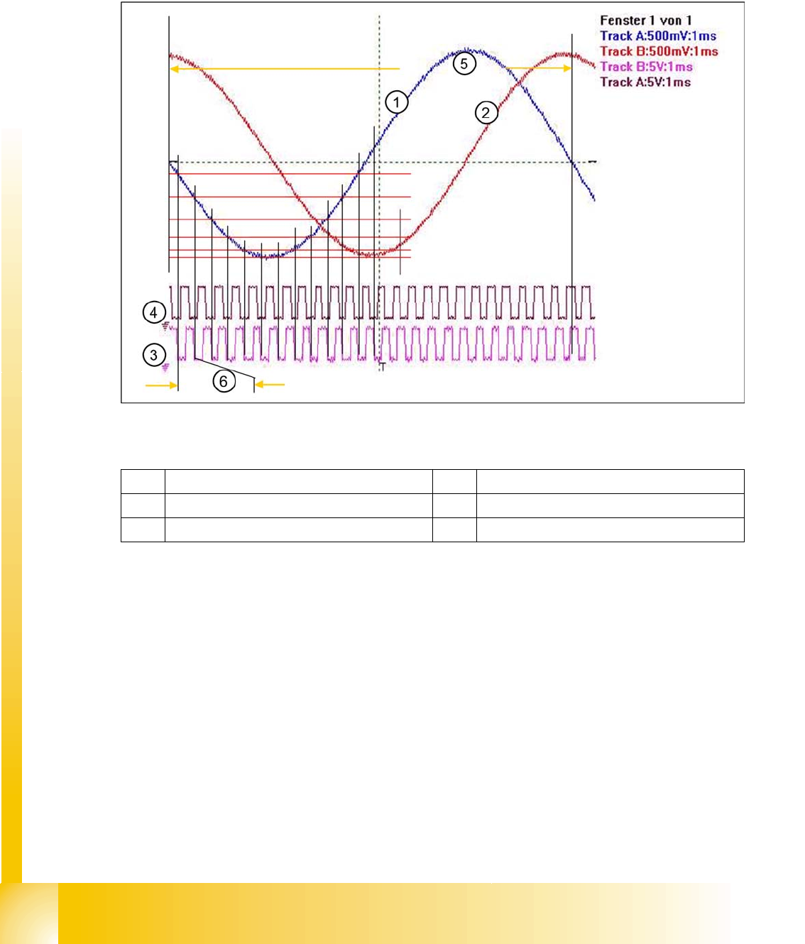
7.1 - 2: Principle signal multiplication at analog Track signals of a gantry axis
Legend
The signal multiplication can be realized as a Schmitt trigger action. During comparison of the analog
and digital axis signals, a signal multiplication of 25 (see diagram above), 10 or just 1 can be recognized.
The track signals of the C&P head axes can only be measured as digital signals i.e. The analog signals
are directly converted in the transmitter housing, without provision of a test connection for the analog
signals.
1 Analog track A signal incremental encoder 4 Digital track B signal at Test connector
2 Analog track B signal Incremental encoder 5 Period time of analog track signal
3 Digital track A signal at Test connector 6 Period time of digital track signal
Axis dynamic
Zero pulse at the position encoder Position measuring system
Student Guide SIPLACE D4 (FSE)
EN 09/2006 Axis dynamic
141
7.1.2 Zero pulse at the position encoder
Each incremental encoder system needs initializing. This means a reference run is executed for each
axis. At the reference run the system searches for a certain position - the signal for this is the Zero pulse.
The Zero pulse is an analoge signal and a ’Schmitt Trigger’ circuit digitizes it.
(Measurement of analog signal by setting the
zero line
at the center of the screen)
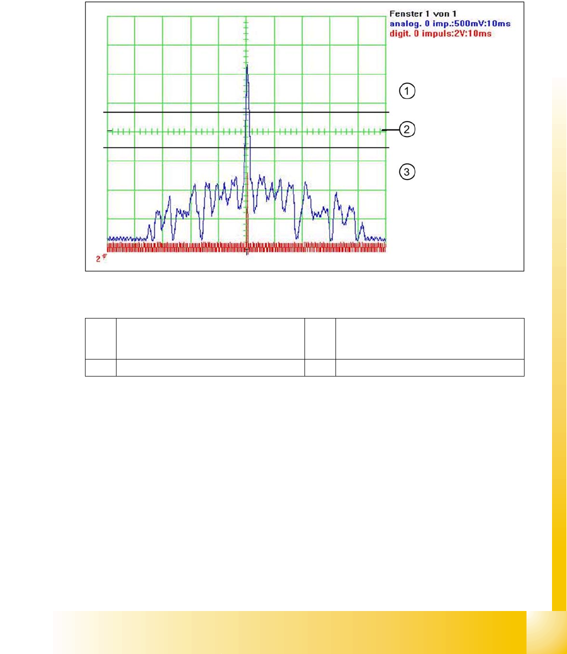
7.1 - 3: Analog and digital zero pulse signal (zero line set at screen center)
Legend
At around 2.5 V the Schmitt trigger circuit issues a brief, high pulse: the zero pulse for the position
measurement system. If the encoder has been installed too near to the incremental scale, one of the
auxiliary pulses could exceed the Schmitt trigger threshold and be mistakenly recognized as the zero
pulse. This would mean that the zero pulse would be recognized in the wrong position on the incremental
scale. This would then lead to a placement offset on the SIPLACE machine. The digital zero pulse is
measured on the gantry head distributor, with a probe at Pin 8 of the test connector. The inverted zero
pulse can be measured at the zero pulse output on the axis test box (or the SIPLACE AxisTester SAT).
1 The analog zero pulse needs to be 0.3 V
higher than the trigger threshold for the digital
zero pulse.
3 Glitches (signal noise) should not override the
limit 0,3 V less than Trigger threshold!
2 Schmitt Trigger Threshold
Axis dynamic
Parts for the axis control Zero pulse at the position encoder
Student Guide SIPLACE D4 (FSE)
Axis dynamic EN 09/2006
142
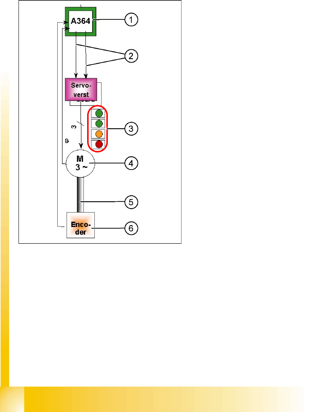
7.2 Parts for the axis control
The control circuit for control the X- and Y-axis in
general consist of the following parts:
Axis board
Servo board (TDS)
3-phase AB linear motor (Y-axis)/
3-phase servo motor (X-axis)
Measurement system (incremental scale and
encoder (read unit))
To protect the motor of the X/Y-axes from
overtemperature, these have an internal
temperature sensor.
Legend:
1. Axis board A364
2. Control signals I
target
"W" and I
target
"U"
3. LED‘s on Servo board:
– Power supply ON
– Servo enable, it the enable signal from the
axis board.
– Display R.M.S. current limiter shorter than
2,5 s.
– Error: Over voltage, -current, -temperature
longer than 2,5 sec.
4. 3-phase AC linear motor (Y-axis) or 3-phase
servo motor with integrated temperature
sensor.
5. Between motor and incremental encoder exist
a fixed mechanically connection.
6. Incremental encoder: transmit the exact
position of the axis The track signals are the
only feedback signals for the axis control
system.
The servo board directly controls the linear motor
(intermediate circuit voltage 250 V) or servo
motor.