00195193-02 SG D4 FSE en (1).pdf - 第234页
C&P12 Placement Head Boards at C&P12 Settings Student Guide SIPLACE D4 (FSE) EN 09/2006 C&P12 Placement Head 219 9.5 Settings 9.5.1 Boards at C&P12 All the settings described in this chapter are head-spec…
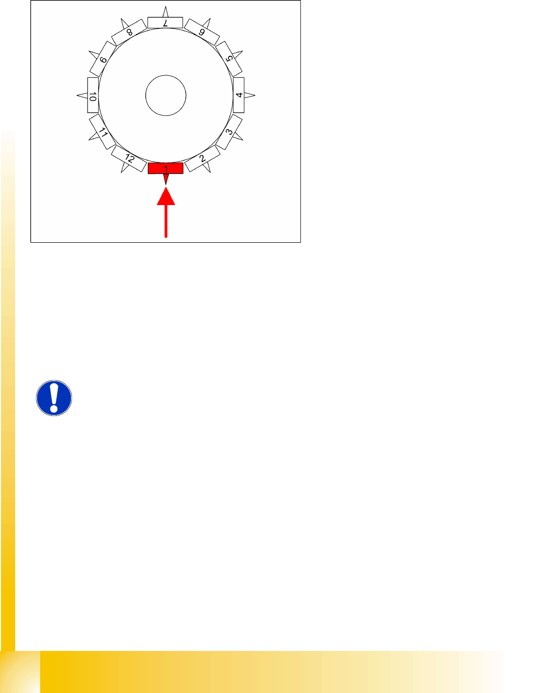
C&P12 Placement Head
Travel Profiles - Placement Z-Axis Up
Student Guide SIPLACE D4 (FSE)
C&P12 Placement Head EN 09/2006
218
9.4.2.2 Placement: Z-Axis Upwards with "Slow Start"
Benefits of Special Mode "Slow Start"
The CO stays on the board even if the soldering paste has a low holding force.
From LRU/LRL 503 and SIPLACE Pro, this
placement type can "only" be programmed in the
CS "for SR/MC 503 stations and higher".
LB down switches:
End position signal for downwards and valve
positioning drive ON for air kiss
Measurement of air kiss pressure during
placement
Start signal for upwards movement
Z-axis starts:
Positioning Z-axis up with reduced starting
speed for the first 44 digits
LB up switches:
Electromagnetic valve for air kiss OFF
Reset LB down signal
Start signal for gantry axes
Z-axis end position signal (Z-axis at 0 position):
Enables vacuum query: "segment airtight?"
after placement (SR/MC503)
Start signal for star axis
NOTE:
However, this option makes the placement procedure around 20 ms longer than
the standard placement procedure.
C&P12 Placement Head
Boards at C&P12 Settings
Student Guide SIPLACE D4 (FSE)
EN 09/2006 C&P12 Placement Head
219
9.5 Settings
9.5.1 Boards at C&P12
All the settings described in this chapter are head-specific and apply here for the C&P12.
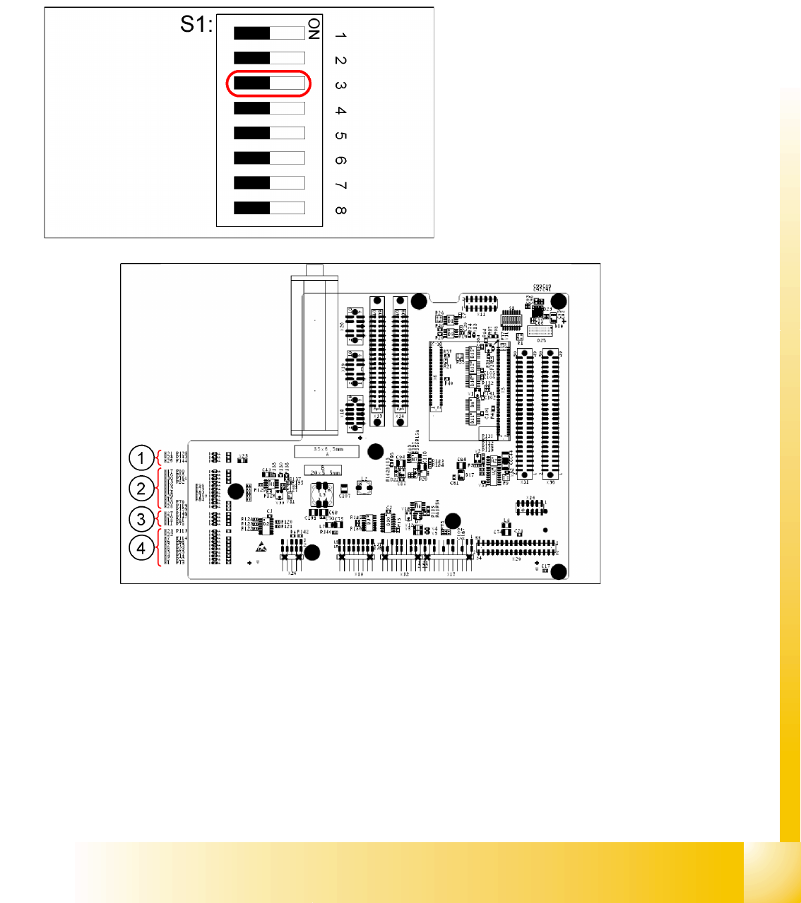
9.5.1.1 Switch S1 on the 8-fold DIP Switch of the Gantry Head Distributor – C&P12
9.5 - 1: LEDs on gantry head distributor
Legend
1. CAN signal
2. Power Supply Unit
3. Head Processor
4. LEDs C&P12
Legend:
S1 – Switch 3:
ON – Test mode (without delay)
OFF – Default state (with delay of 3.6 ms+/-
300 us) means: Z-axis moves downwards, the
top LB is released and the LB down is enabled
after a delay of 3.6 ms.
C&P12 Placement Head
Settings Boards at C&P12
Student Guide SIPLACE D4 (FSE)
C&P12 Placement Head EN 09/2006
220
Description of LEDs for C&P12:
9.5.1.2 SP_12 Digital intermediate distribution board (00330648-05)
Labeling on the board Labeling on the circuit
diagram
Explanation
+V – LB H23 OK + 15V light barrier
+V – LB H22 Error +15V light barrier
Z – O H7 Z-axis is up
Z-U H6 Z down has switched
ERR-ZH H2 Overload SM feed-in
ERR – DP H8 Overload SM rotary axis
ERR-BA H3 Overload SM reject
LB – ZH H4 Light barrier SM feed-in
LB – DP H5 Light barrier SM rotary axis
LB-BA H1 Light barrier SM reject
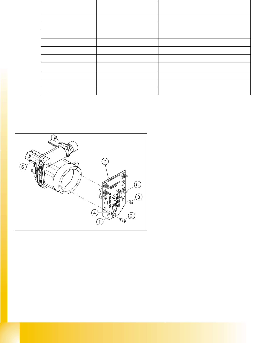
Legend:
1. Intermediate distribution board
2. Spacer bolt M3x10
3. Spacer bolt M3x10
4. Spacer bolt M3x10
5. Spacer bolt M3x10
6. Front section of C&P head
7. Connectors X1 and X2 (on the rear side)
The intermediate distribution board (1) is fixed to
the front part (6) with four spacer bolts (items 2, 3,4
and 5). The pressure sensor is located above the
spacer bolts (5), on the back of the intermediate
distribution board. The cover of the intermediate
distribution board is fixed with push buttons.