00195193-02 SG D4 FSE en (1).pdf - 第270页
Modular conveyor Description of the functions Conveyor Control TSP 301 S tudent Guide SIPLACE D4 (FSE) Modular conveyor EN 09/2006 254 1 1.1.10 Conveyor Control TSP 301 The conveyor control TSP 301 supp orts the followin…

Modular conveyor
"Alignment Pin" option Description of the functions
Student Guide SIPLACE D4 (FSE)
EN 09/2006 Modular conveyor
253
11.1.7 "Alignment Pin" option
This option is for unfavorable lenght/width relationship, for cut outs at the leading edge at a PCB board
or for wide and short boards. (This also allow to combine the conveyor systems when the PCB have a
steped leading edge.) Mechanical stopper pins are mounted on a flexible conveyor side at the lifting
table. This option can be enabled or disabled with a switch. The lifting table move up, so that the top of
the pin is at the same height as the board. The laser recognize the PCB board and the conveyor stops
after a defined time and the clamping is completed. The clearance under the PCB board is reduced to
25mm.
11.1.8 Lifting table
Depending on the version (single/dual conveyor), one or two independent lifting tables are used in each
placement area. The lifting table drive works indirectly via a pneumatic cylinder controlled by a 5/3-way
valve. PCB‘s of different thickness will automatically be compensated for. The PCB is guided in the Z
direction at four points on the lifting table plate. The lifting path is determined via a distance measuring
system.
The top position of the lifting table is identified by the position measuring system and a fork light barrier
for lane A and B. The top position of the lifting table and the correct clamping of the board are checked
in current mode via the conveyor motors. The lowest lifting table position is detected by the incremental
measuring system and an end position BERO on the pneumatic cylinder. The default clearance under
the PCB is 40 mm.
If you use a dual conveyor as an single conveyor you must couple both lifting tables.
11.1.9 Firmware functions
Transporting, clamping, temporarily storing the PCBs, positioning the PCB using a laser light barrier,
mechanical stopper for long PCBs as an option
Single functions for controlling the conveyor
Adjusting the conveyor width
Controlling the inputs/outputs (using the Sitest program)
Downloading the firmware via SITEST
Setting the conveyor parameters (conveyor speed) in Sitest
Synchronous transport mode
Calibrating the conveyor sides (SITEST function)
Saving the machine conveyor data
NOTE:
The red, 74 mm board supports, previously used for S20, F4, S25HM, S27HM,
F5HM, HS50, HS50+, are not suitable for use in HS60, HF, X or D machines.
Use the black 94 mm board supports for HS60, HF, X and D machines.
Modular conveyor
Description of the functions Conveyor Control TSP 301
Student Guide SIPLACE D4 (FSE)
Modular conveyor EN 09/2006
254
11.1.10 Conveyor Control TSP 301
The conveyor control TSP 301 supports the following options:
Flexible left conveyor side fixed (default: right conveyor side fixed)
"Long PCB" option
PCB Alignment pin
Vacuum tooling
PCB barcode
SMEMA interface, SIEMENS (option)
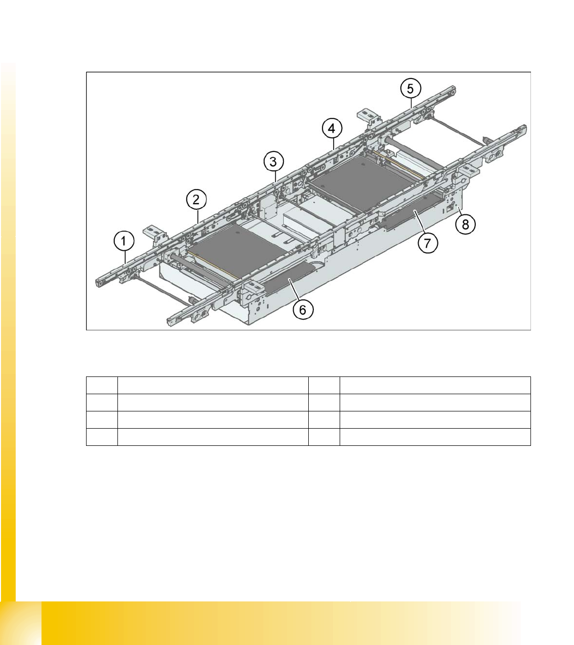
11.1.11 Structure of the single conveyor
11.1 - 1: PCB transport - single conveyor
Legend
In SIPLACE machines, the single conveyor system consists of an input conveyor, two placement areas,
the intermediate conveyor and the output conveyor. The conveyor has an automatic width adjustment
unit and a lifting table for clamping the PCB.
1 Eingabeband 5 Ausgabeband
2 Placement area 1 6 Lifting table, placement area 1
3 Intermediate conveyor 7 Lifting table, placement area 2
4 Placement area 2 8 Mounting frame
Modular conveyor
Structure of the dual conveyor Description of the functions
Student Guide SIPLACE D4 (FSE)
EN 09/2006 Modular conveyor
255
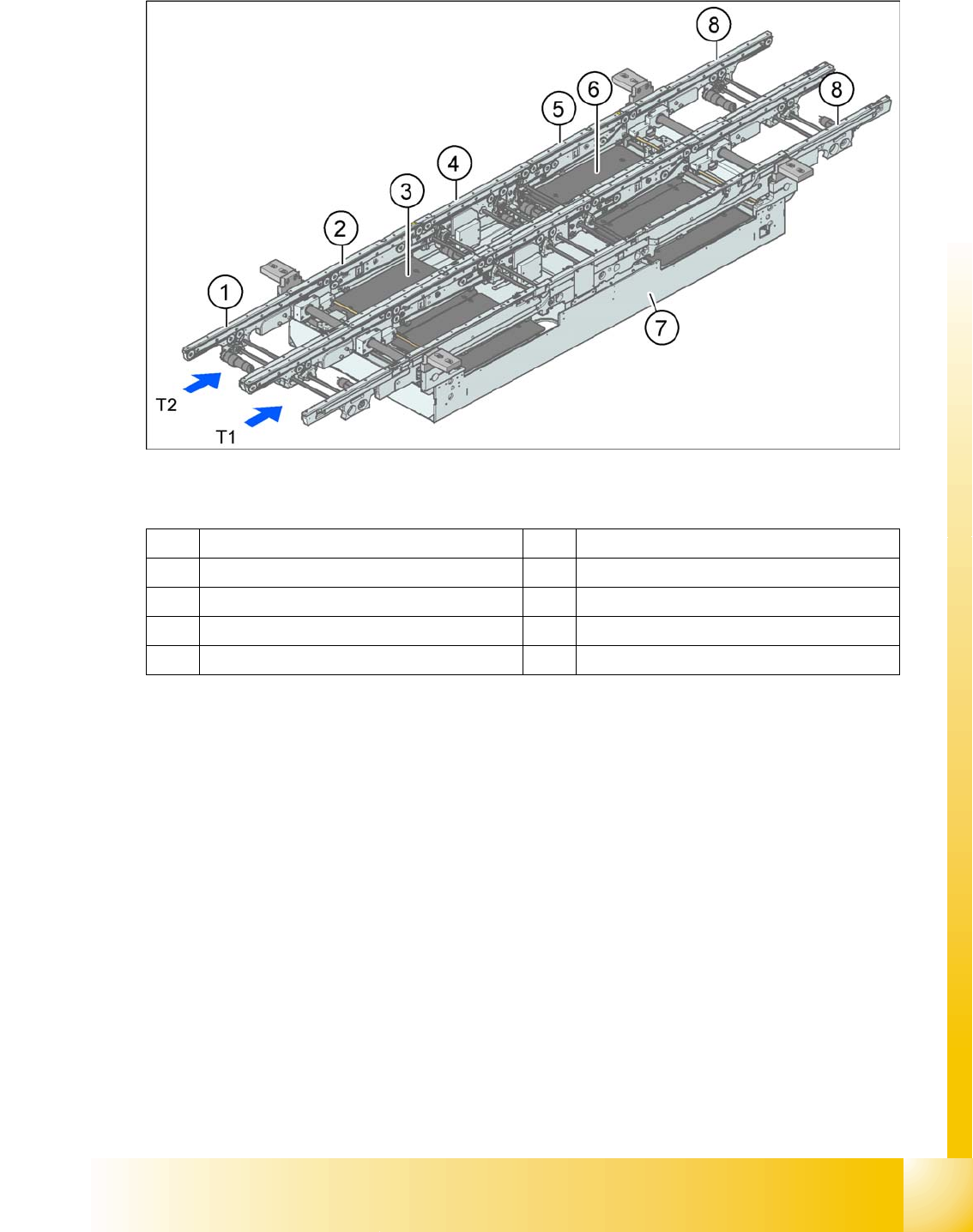
11.1.12 Structure of the dual conveyor
11.1 - 2: PCB transport - dual conveyor (HF)
Legend
The dual conveyor has two conveyor tracks. In the standard version, the fixed conveyor side of each
conveyor track is on the right-hand side.
1 Eingabeband 6 Lifting table, placement area 2
2 Placement area 1 7 Mounting frame
3 Lifting table, placement area 1 8 Ausgabeband
4 Intermediate conveyor T1 Conveyor track 1
5 Placement area 2 T2 Conveyor track 2