00195193-02 SG D4 FSE en (1).pdf - 第129页
Services to the machine Power Supply Unit Voltages in the Power Supply Unit After Switching On S tudent Guide SIPLACE D4 (FSE) Services to t he machine EN 09/2006 122 6.2.8 V oltages in the Power S upply Unit Af ter Swit…
Services to the machine
Transformer 1 Power Supply Unit
Student Guide SIPLACE D4 (FSE)
EN 09/2006 Services to the machine
121
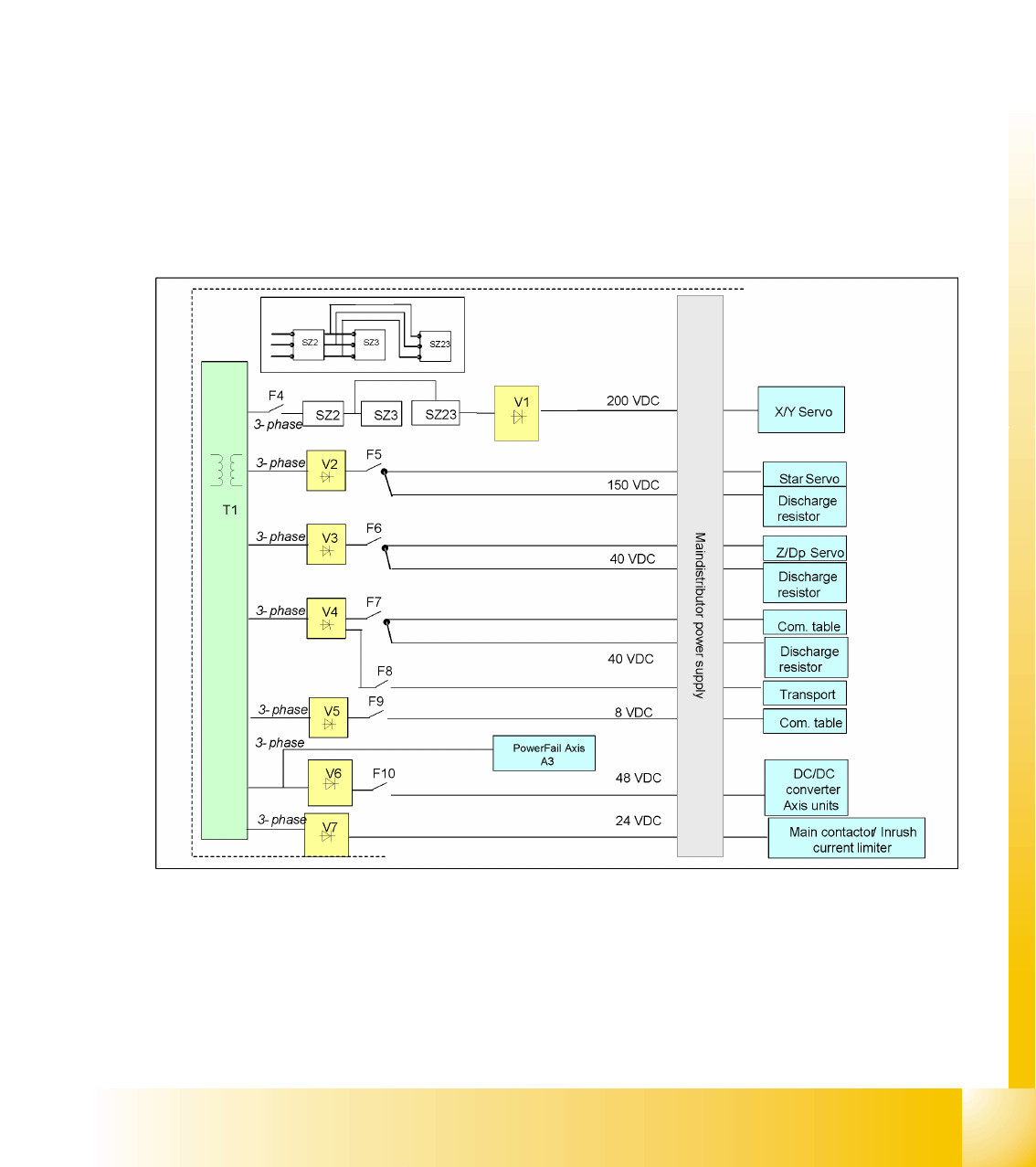
6.2.7 Transformer 1
The main task of transformer T1 is to supply power to the X/Y axes, protected by fuse F4, star axes by
fuse F5 and Z/DP axes by fuse F6. Contactors SZ2, SZ3 and SZ23 are a fixed part of the electrical safety
concept. In a fault event, e.g. open cover, the servos are disconnected from the energy.
The power supply provides the following voltages:
Secondary side of transformer (voltage before and after the rectifiers):
3x146 VAC for the servo amplifier of the X and Y axes (200 VDC)
3x24 VAC for the servo amplifier of the star axis. (150 VDC)
3x32 VAC for the servo amplifier of the Z/DP axis (40 VDC)
3x32 VAC for CO table and conveyor (40 VDC)
3x8 VAC for CO table (8 VDC)
3x40 VAC for the DC/DC converter and the power fail axis (48 VDC)
3x24 VAC for the inrush current limiter (34 VDC)
6.2 - 3: Overview of transformer T1
Services to the machine
Power Supply Unit Voltages in the Power Supply Unit After Switching On
Student Guide SIPLACE D4 (FSE)
Services to the machine EN 09/2006
122
6.2.8 Voltages in the Power Supply Unit After Switching On
When the main switch is activated, the following voltages are generated, sent to the modules and
released or held ready for release:
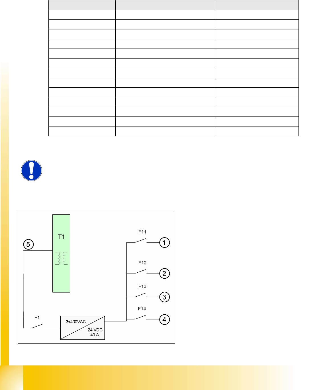
6.2.9 Power Pack 24 V
Voltages Module State
250 VDC X/Y servo module not enabled
150 VDC Star servo not enabled
34 VDC PCB handling system Released up to SZ2
24 VDC tape cutter not enabled
34 VDC SZ1 main power inrush current enabled
52 VDC DC/DC converter main power supply enabled
52 VDC Camera illumination enabled
40 VDC Power fail A3 enabled
42 V DC Z/DP axes enabled
40 VDC Feeder table plate enabled
28 VDC monitor enabled
24 VDC fan enabled
230 or 115 or 240 VAC service socket independent of the main switch
NOTE:
The service socket can only be used if the placement system is connected to
the main power supply with a 5-conductor cable (L1, L2, L3, N, PE).
The power pack is fed from the primary side of the
transformer.
It is supplied via 3 phases.
Legend:
1. Main distributor (sector 2 X5)
Subdistributor (sector 4 X5)
2. K1 protective combination relay (A1+)
Micro box PC (machine controller X4)
3. Axis unit 1/2 (X8_7,X9_7)
Box PC (station computer X3)
4. Conveyor (X6_2)
Monitor 1/2 (X2_1,X2_3)
5. 3 phases
The data in brackets are for the output connector
plugs in the voltage supply rack unit.
Services to the machine
Power Pack 5 V Power Supply Unit
Student Guide SIPLACE D4 (FSE)
EN 09/2006 Services to the machine
123
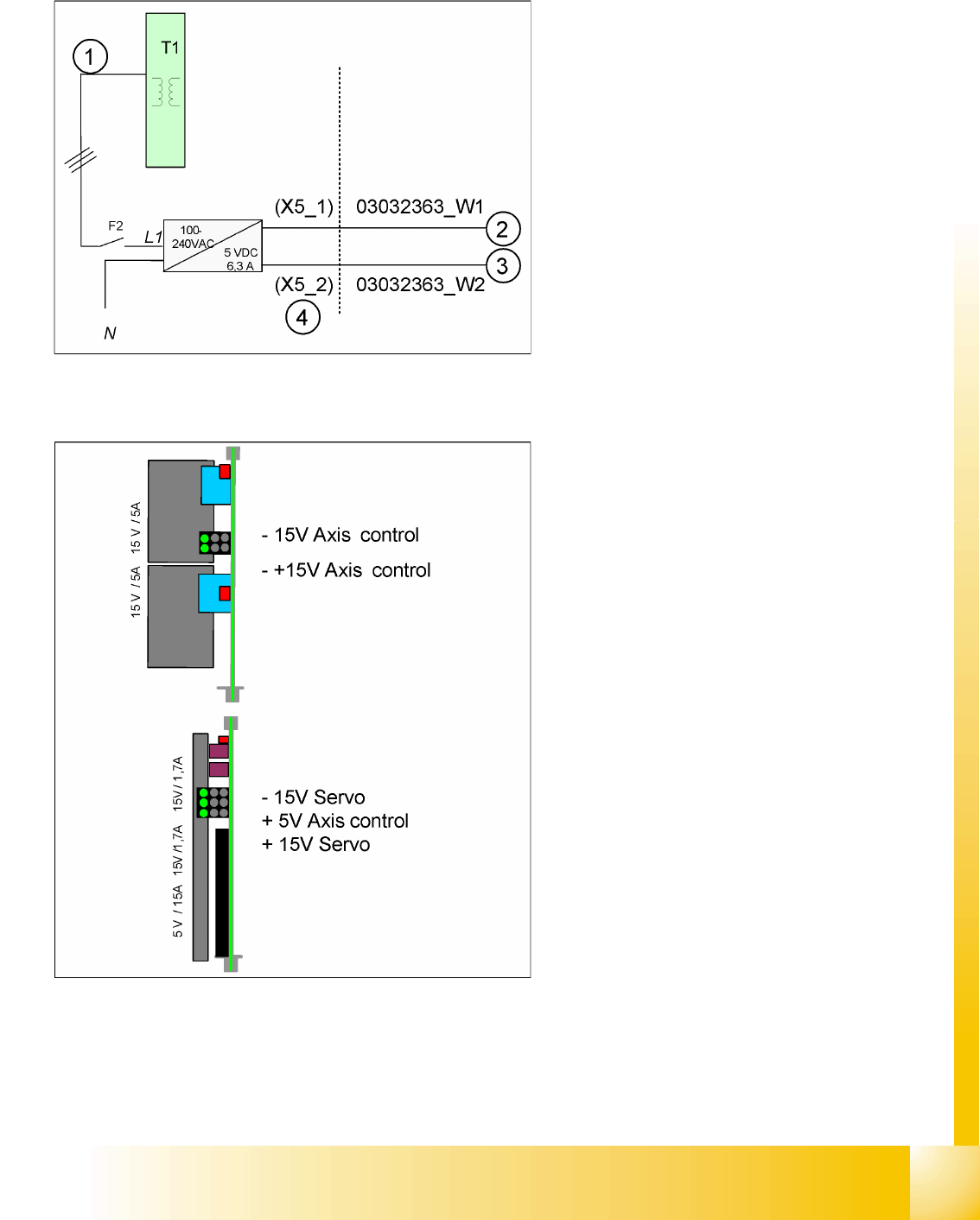
6.2.10 Power Pack 5 V
6.2.11 Power Supply for Axis Unit
The power pack is fed from the primary side of the
transformer.
The 5 V power pack is fed after fuse F2, with one
phase (L1).
Legend:
1. 3-phase up to fuse
2. +5 V distributor sector 2 for cutter 2/3
3. +5 V distributor sector 4 (USB, video
multiplexer, cutter 1/4)
4. The data in brackets are for the output
connector plugs in the voltage supply rack
unit.
After activating the main switch, the axis unit is
supplied with power from the main power supply,
via X8 for axis unit 1 and X9 for axis unit 2. It is
supplied with 48 VDC and the following voltages
are generated:
+/-15 V and +/-15/5 V
This DC/DC converter generates the 5V and +/-
15V needed for the servo board and the axis
controller