00195193-02 SG D4 FSE en (1).pdf - 第131页
Services to the machine Power Supply Unit Voltage Supply for SIPLACE Vision Illumination S tudent Guide SIPLACE D4 (FSE) Services to t he machine EN 09/2006 124 6.2.12 V oltage Supply for SI PLACE V ision Illumination 6.…
Services to the machine
Power Pack 5 V Power Supply Unit
Student Guide SIPLACE D4 (FSE)
EN 09/2006 Services to the machine
123
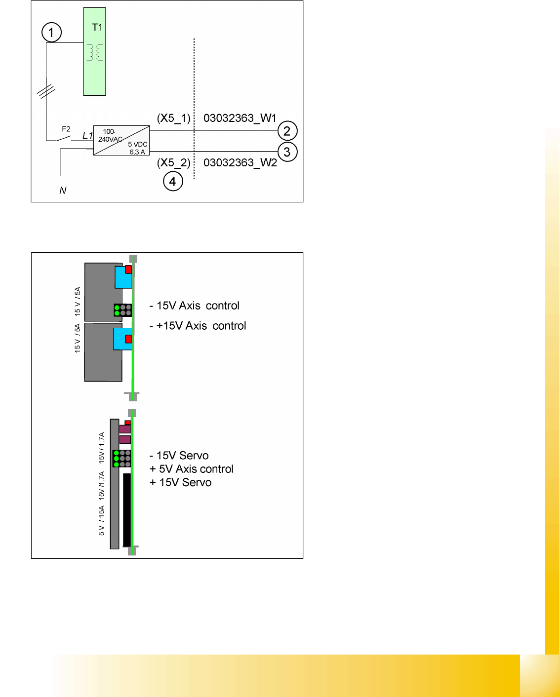
6.2.10 Power Pack 5 V
6.2.11 Power Supply for Axis Unit
The power pack is fed from the primary side of the
transformer.
The 5 V power pack is fed after fuse F2, with one
phase (L1).
Legend:
1. 3-phase up to fuse
2. +5 V distributor sector 2 for cutter 2/3
3. +5 V distributor sector 4 (USB, video
multiplexer, cutter 1/4)
4. The data in brackets are for the output
connector plugs in the voltage supply rack
unit.
After activating the main switch, the axis unit is
supplied with power from the main power supply,
via X8 for axis unit 1 and X9 for axis unit 2. It is
supplied with 48 VDC and the following voltages
are generated:
+/-15 V and +/-15/5 V
This DC/DC converter generates the 5V and +/-
15V needed for the servo board and the axis
controller
Services to the machine
Power Supply Unit Voltage Supply for SIPLACE Vision Illumination
Student Guide SIPLACE D4 (FSE)
Services to the machine EN 09/2006
124
6.2.12 Voltage Supply for SIPLACE Vision Illumination
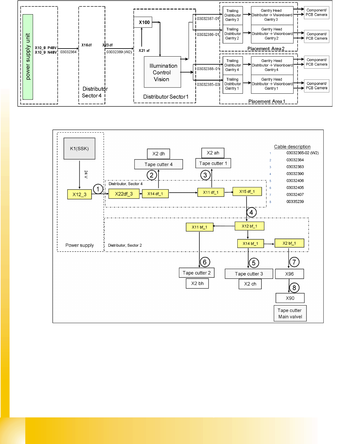
6.2.13 Power Supply Tape Cutter
6.2 - 4: Power supply tape cutter
The tape cutters are arranged in a parallel and a serial mode. The tape cutters in sector 2 and sector 3
are serial, tape cutters in sector 1 and sector 4 are also arranged in serial mode.
The pneumatic valves require 24 V, while the tape cutter control board is supplied with 5 V from the
power pack in the power supply unit.
Services to the machine
Safety and Signaling Circuit Power Supply Unit
Student Guide SIPLACE D4 (FSE)
EN 09/2006 Services to the machine
125
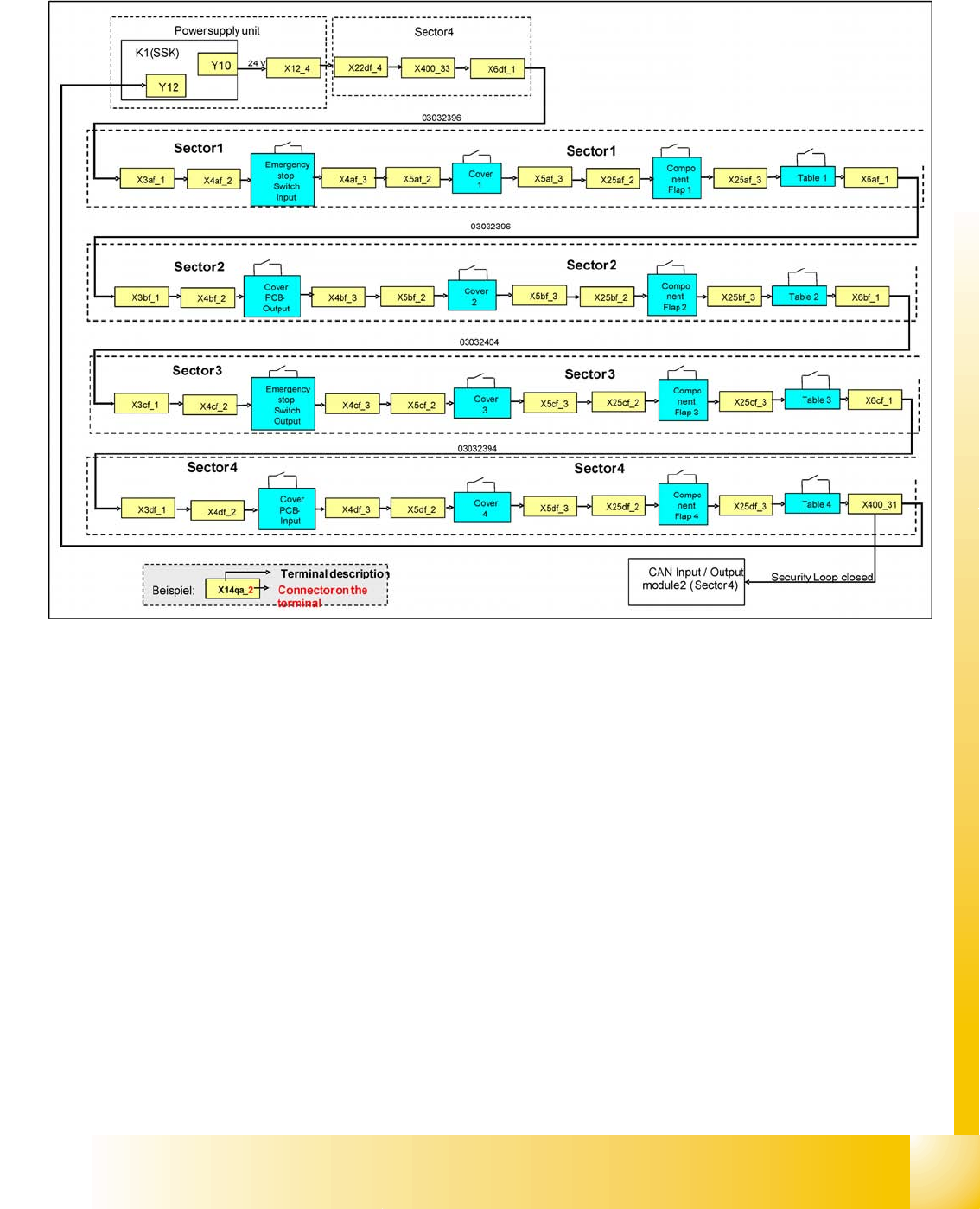
6.2.14 Safety and Signaling Circuit
6.2.14.1 Emergency Stop Circuit (Safety Loop)
6.2 - 5: Safety loop
Following contacts are switched in serial and build the safety loop:
4 switches for protective hoods.
Switch for conveyor cover in input and output areas
Contact on component changeover table
Make sure that the emergency stop button is not pressed (input & output conveyor).
Feeder cover at each location
Description of emergency stop circuit:
When the emergency stop circuit is closed 24 V will be present. A further 24 V signal is sent as
EMER-
GENCY STOP circuit OK
to the CAN I/O module, indicating that the covers are all closed and that the
CO tables are connected.