00195193-02 SG D4 FSE en (1).pdf - 第307页
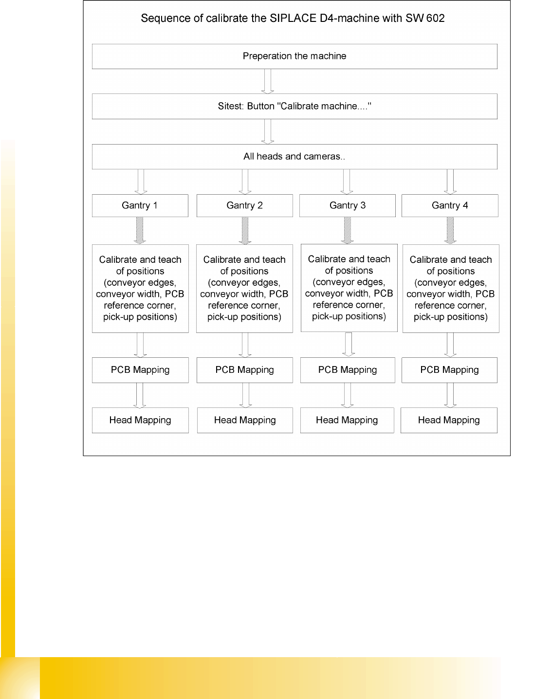
Sitest Calibration Calibration in general S tudent Guide SIPLACE D4 (FSE) Sitest EN 09/2006 288 12.2.1 Calibration in general 12.2 - 1: General sequence to calibrate the machine

Sitest
Buttons in the Main Menu and Submenus Calibration
Student Guide SIPLACE D4 (FSE)
EN 09/2006 Sitest
287
12.2 Calibration
Equipment and Testing Tools
SITEST, version 602.xx or higher
Calibration device
Version II transparent S/F/HS --> 00316308-03
Version III not transparent HF/X/D machines with C&P6/12 and Twin Head --> 03010565-01
Version SST 23 X machine C&P20 --> 03034148-01
Nozzles, type 1235, 956, 517, 518, nozzle for ZPC D-axis TH 03008862-03
Setting gauge for S tables
PCB for calibration of conveyor width
DANGER: RISK OF INJURY!
The gantry may move during some of the following procedures.
Therefore, before you begin with any of these procedures make sure that you
and everyone else stay physically clear of the travel range of the gantries.
X Also, sure, that no objects are in the way.
NOTE:
Before you begin with the calibration, you must reference the heads and the
gantries.
During calibration, unused gantries will automatically be moved to their parking
position.
To completely calibrate the machine, go to
Calibrate machine...
and select
the
Calibrating the entire machine
menu. This provides all the required
calibration functions.
Sitest
Calibration Calibration in general
Student Guide SIPLACE D4 (FSE)
Sitest EN 09/2006
288
12.2.1 Calibration in general
12.2 - 1: General sequence to calibrate the machine
Sitest
Precondition for Calibration of SIPLACE D Calibration
Student Guide SIPLACE D4 (FSE)
EN 09/2006 Sitest
289
12.2.2 Precondition for Calibration of SIPLACE D
X Start SITEST.
X by selecting the menu items
MAIN VIEW
,
Overall reference run
, to start the reference run for all
gantries and heads.
X Configure the nozzle changer and check the component levels.
Precondition for calibrate the nozzle changer
Each magazine in the NC must be configured with a nozzle type.
There should be no nozzle at segment 1 .
Each magazine must at least have a nozzle present and configured (1) in garage 1 .
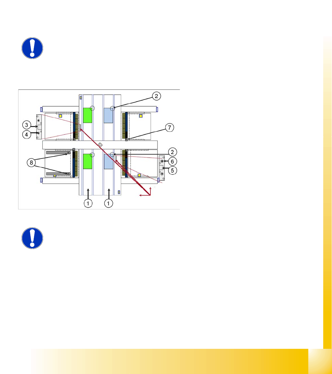
12.2.3 Calibration positions in the machine
NOTE:
When configuring the C&P12, you can also set all magazines to "empty" and
the head to "full".
Legend
1. Transport direction
2. PCB reference corner PA1/2 lanes 1 and 2
3. Calibration position PA2
4. Machine zero point PA2
5. Calibration position PA1
6. Machine zero point PA1
7. Calibration position of nozzle reject station at
each location
8. Position of setting gauge for CO tables track 1
and track 72 at each location
NOTE: Some calibrations require that you attach nozzles on the placement
heads.
Use nozzle type 956 for C&P12. Make sure that all nozzles have been attached
correctly, otherwise measuring will lead to incorrect results. You may need to
place calibration tools in the calibration pockets.
Before you place the calibration tool, make sure that it is clean. Also, be sure
that you insert it into the "calibration pocket" with its print of the fiducial structure
on the bottom.