00195193-02 SG D4 FSE en (1).pdf - 第237页
C&P12 Placement Head Settings Overview of Set tings for C&P12 (DLM3) S tudent Guide SIPLACE D4 (FSE) C&P12 Placement Head EN 09/2006 222 9.5.2 Overview of Sett ings for C&P12 (DLM3) X13, 10-pole Test conn…
C&P12 Placement Head
Boards at C&P12 Settings
Student Guide SIPLACE D4 (FSE)
EN 09/2006 C&P12 Placement Head
221
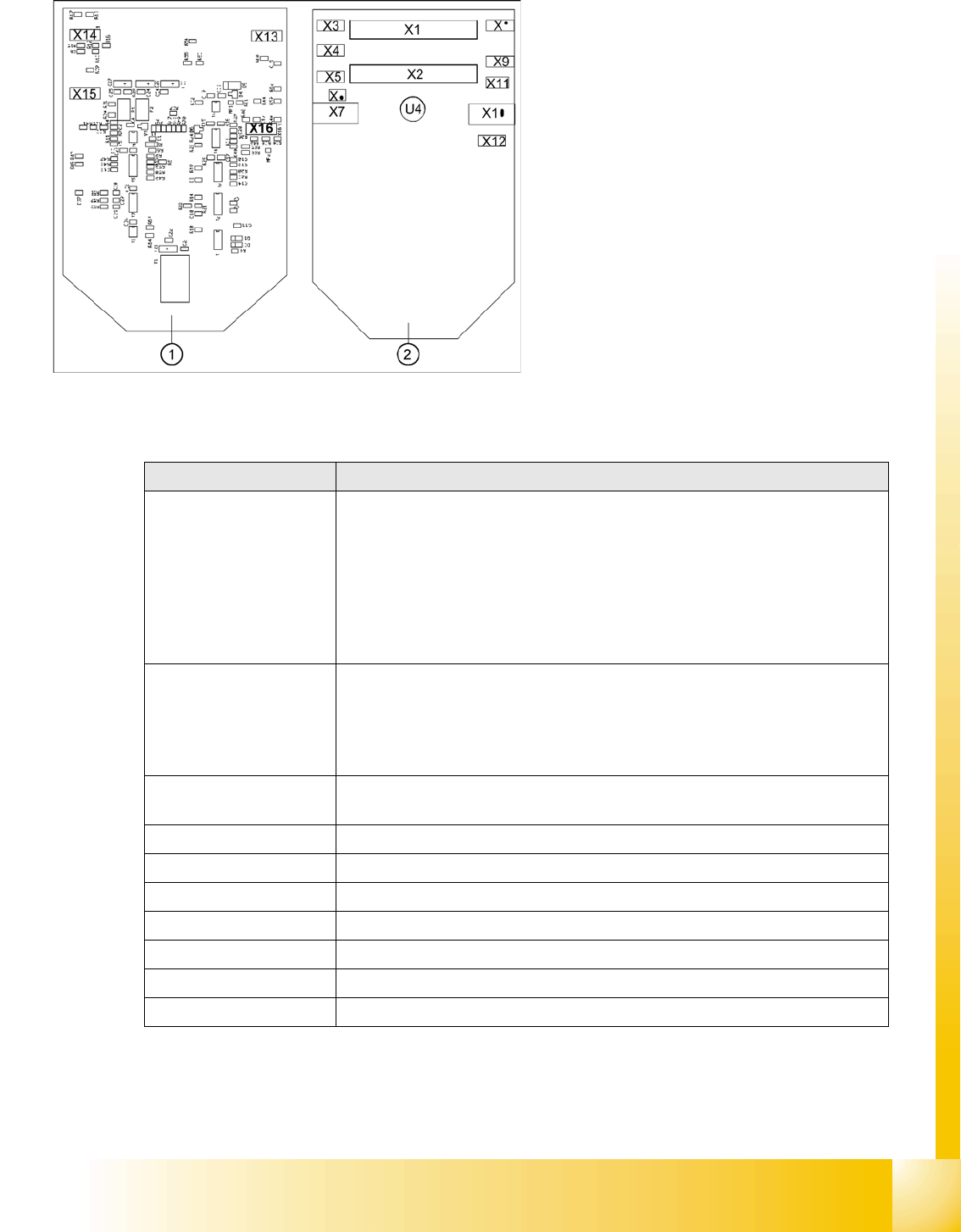
The following supply voltages and signals are routed by the intermediate distribution board to the
individual placement head modules or to the head board:
Legend:
1. Front of the intermediate distributor
2. Back of the intermediate distributor
U4 = pressure sensor
Two 40-pin ribbon cables run from plug X1 and X2
on the intermediate distribution board to socket
X14 / X13 on the head board.
Connectors Description
X1, 40-pole Connected to plug X14 on the head board
Voltage supply, tacho and track signals for the Z-axis drive
Signal from light barrier "Z-axis in top position"
Signal from light barrier "Z-axis in bottom position" (sensor stop signal)
Control signal for the forced air valve
Supply voltage +5 VDC, ±15 VDC
Reference point signal for the DP-axis
Track signals for the DP-axis
X2, 40-pole Connected to plug X13 of the gantry head distributor
Voltage supply and track signals for the star-axis drive
Reference point for the star-axis
Analog forced air pressure value
Supply voltages +5 VDC, ±15 VDC, +24 VDC
X3, 10-pole Connection for the Z-motor and Z-tacho signal (Tacho signal is not use on the HF-
machine)
X4, 10-pole Connection for the Z-axis track signals
X5, 10-pole Connection for the star motor
X6, 6-pole Connection for the forced air valve
X7, 10-pole Connection for the DP-axis track signals
X10, 10-pole Connection for the "Z-axis up" signal
X11, 8-pole Connection for the light barrier "Z-axis down" signal (sensor stop signal)
X12, 10-pole Connection for the star-axis track signals
C&P12 Placement Head
Settings Overview of Settings for C&P12 (DLM3)
Student Guide SIPLACE D4 (FSE)
C&P12 Placement Head EN 09/2006
222
9.5.2 Overview of Settings for C&P12 (DLM3)
X13, 10-pole Test connection for the Z-axis track signals
X14, 10-pole not used
X15, 10-pole Test connection for the Star-axis track signals
X16, 10-pole Test connection for the Dp-axis track signals
Connectors Description
Description Tools &Equipment Adjustments
Mounting the star onto the motor
shaft of the star motor
Adjustment with the power pack and
the gauge for the star
Check the magnetic neutral position
in SITEST.
(max. deviation 95 digits)
Determine zero point correction for
the star
Gauge for zero point correction /
Sitest
Determine zero point correction
value in SITEST
--> enter positions.
Switch position on DLM3 (resolution
of track signals 10 - 25)
nothing HF/X/D machines at switch position
25
DP-axis Incremental encoder
adjustment to the glass scale
(segment)
Parallel pin 1,4 - 1,6 mm Distance 1,5 mm
Adjustment mechanical position of
valve drives
Distance gauge 0.2 mm 0.2 mm distance plunger to the valve
frame
Light barrier bottom position Z-axis Parallel pin 1,0 mm Distance 1,0 mm
Clamping device on Z-belt Tension jack must lie on the belt
teeth at the top and bottom.
Belt tension of the Z-axis Belt tension measurement device Belt tension 280 +/- 5 Hz
Setting the stop for the Z-axis Gauge for the Z-mechanical end
stop (03019865-01)
Correct position are necessary to
determine the zero point correction
Z-axis.
Mechanical adjustments Air kiss
tubes on the star
Check with your eyes Check the distance between
incremental encoder dp and air kiss
tubes.
Adjustments tube for air kiss supply feeler gauge Air kiss tubes should be approx. 0,7
mm over the frame of the circular
guide
Adjustments air pressure values Compressed air testing device 150 mbar on open 9x4 nozzle
C&P12 Placement Head
Setting the resolution on the star axis Settings
Student Guide SIPLACE D4 (FSE)
EN 09/2006 C&P12 Placement Head
223
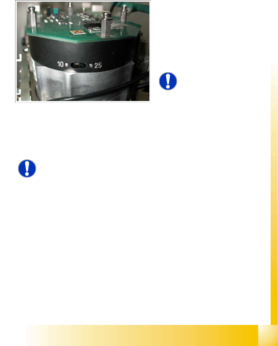
9.5.3 Setting the resolution on the star axis
9.5.4 Setup of the Digital Rotary Transducer of the DP - Axis
Remove sleeve 1 and insert the Star zero point gauge, in order to mechanically fix the Star.
Now, remove sleeve 4 or the sleeve 2 for the 6 segment C&P head as well and align the transducer.
With the help of a parallel pin, set the rotary transducer of the DP - axis to 1.5 mm, parallel to the
glass pane of the segments.
Legend:
1. The switch for the star axis resolution is
directly beneath the C&P head on the star
motor.
X Check the setting of this switch (1).
HS-60 and S-27 HM: Switch position 10
D, HF/HF3 and X machines: Switch position
25
NOTE:
Only setting the switch, if the machine
power is off.
NOTE:
Make sure that a 1.4 mm test probe can be easily passed through and that a
probe with 1.6 mm can not be passed through.