00195193-02 SG D4 FSE en (1).pdf - 第182页
Axis dynamic Axis control Z-Axis Axis control C&P head axes Student Guide SIPLACE D4 (FSE) EN 09/2006 Axis dynamic 169 7.5.4 Axis control Z-Axis The Z-axis is driven via a DC servo motor. Activation is via a control …
Axis dynamic
Axis control C&P head axes Axis control Star Axis
Student Guide SIPLACE D4 (FSE)
Axis dynamic EN 09/2006
168
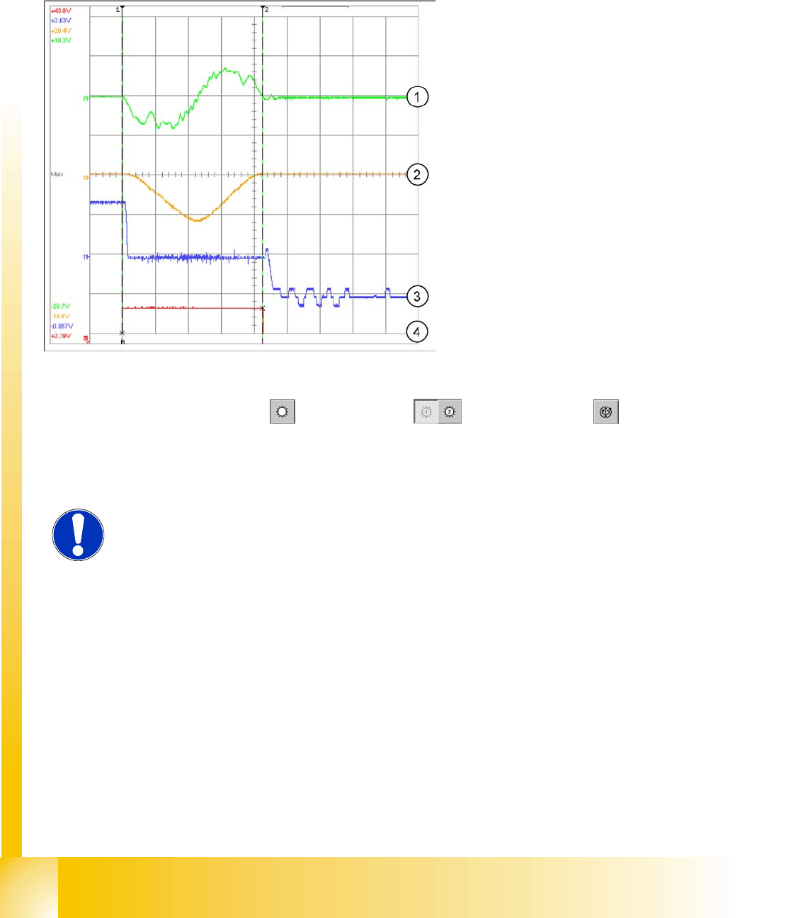
7.5.3.1.3 Example for dynamic with the control signal of the Vnom. output
The star axis dynamics are checked in the permanent star step. A motor phase current (control signal 1)
is emitted at the V nominal output of the axis test box. The uncommutated current setpoint signal
(signal 3) shows increased friction axis values.
The positioning time for the star axis is 43 +/-3 ms for the C&P12.
SITEST:
X Select
C&P heads
==>
Select head
==>
Axis functions
==>
Select the star axis
==>
Star continuous operation
==> Entry: waiting period
500 ms
==>
Accept
.
X Press the START button is required.
Legend:
1. Current signal for axis adapter
2. Control signal (Axis testbox V nom.) current
target value: 2V/Div
3. Deviation of position 500mV/Div
4. End signal
Time basis: 10ms/Div
Positioning time: 43ms +/3ms
1 step = 30000 digits = 30 degrees
NOTE:
If the dynamics are significantly slower, check the friction blocks on the star and
the installation of the star in the drive's magnetic neutral position.
Axis dynamic
Axis control Z-Axis Axis control C&P head axes
Student Guide SIPLACE D4 (FSE)
EN 09/2006 Axis dynamic
169
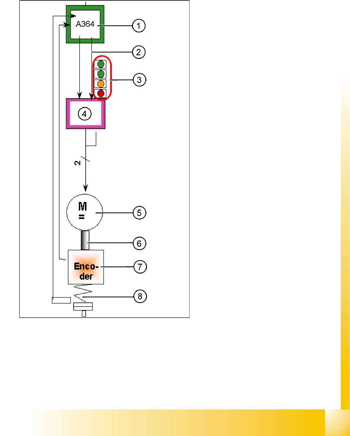
7.5.4 Axis control Z-Axis
The Z-axis is driven via a DC servo motor.
Activation is via a control signal (second control
signal = 0) from the processor of the A364 I
-target
"W"
and I
-target "U"
= 0. The intermediate circuit
voltages is approx. 60V.
Legend:
1. Axis board A364
2. Control signal I nom "W"
3. LED‘s on Servo board:
– Power supply ON
– Servo enable, it the enable signal from the
axis board.
– Display R.M.S. current limiter shorter than
2,5 s.
– Error: Overvoltage, overcurrent,
overtemperature or nominal current
overshoot longer than 2.5 sec.
4. Servo amplifier
5. DC motor.
6. Between the motor and the incremental
encoder exist a fixed mechanical combination.
7. Incremental encoder: Transmits the exact
position of the axis (track signals).
8. Elastic mech. Combination (Belt) and light
barrier below, for the fast recognition of the
lower position.
The servo board controls the DC motor directly.
Axis dynamic
Axis control C&P head axes Axis control Z-Axis
Student Guide SIPLACE D4 (FSE)
Axis dynamic EN 09/2006
170
7.5.4.1 Check the dynamic Z-Axis
7.5.4.1.4 Test set up
The positioning time for the Z-axis is 21 +/-1 ms for the C&P12.
X Move the gantry in the Service position, so that the Z-axis move in a free space.
SITEST
X Select
C&P heads
==>
Select head
==>
Axis functions
==>
Select the Z-axis
==>
Select the permanent axis run,
edit the values in digits and accept.
Target position 685 digits and Position mode = absolute" ==> "Sart".
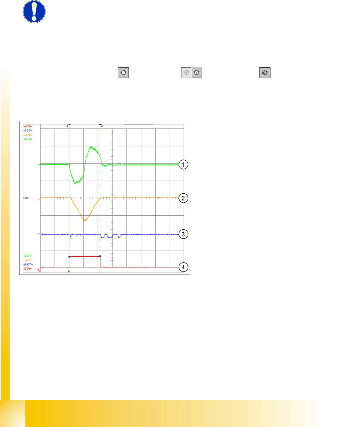
7.5.4.1.5 Example for dynamic with the control signal of the Vnom. output
NOTE:
The measurement procedure is prepared and performed identically to that for
the star axis.
Legend:
1. Current signal for axis adapter
2. Motor current signal (at V nom. output) current
target value: 2V/Div
3. Deviation of position 500mV/Div
4. End signal
Time basis: 10ms/Div
Positioning time: 21 ms -1 ms
Path: 685 digits