00195193-02 SG D4 FSE en (1).pdf - 第52页
Overview General Overview of Assemblies Changeover Table Components S tudent Guide SIPLACE D4 (FSE) Overview EN 09/2006 52 3.2.5.2 Overview of S-Feeder Description: 9 differ ent feeders are eno ugh to proce ss tapes with…
Overview
Changeover Table Components General Overview of Assemblies
Student Guide SIPLACE D4 (FSE)
EN 09/2006 Overview
51
3.2.5 Changeover Table Components
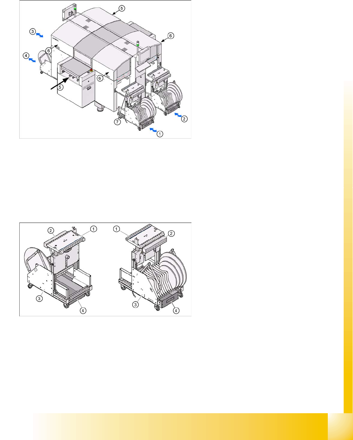
3.2.5.1 Setting the Height of the CO Table
The CO table can be manually set to the following PCB transport heights
830 mm PCB transport height
900 mm PCB transport height
930 mm PCB transport height
950 mm PCB transport height
Legend:
1. CO table location 1
2. CO table location 2
3. CO table location 3
4. CO table location 4
5. Transport direction
6. The button for docking and undocking the CO
changeover tables is located under the feeder
cover flap of each CO table
7. Switch to lower the table after undocking
Legend:
1. Feeder table plate
2. Communication unit
3. Tape container
4. Waste container for tape cuttings
Overview
General Overview of Assemblies Changeover Table Components
Student Guide SIPLACE D4 (FSE)
Overview EN 09/2006
52
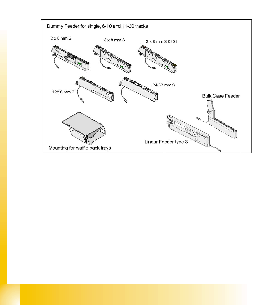
3.2.5.2 Overview of S-Feeder
Description: 9 different feeders are enough to process tapes with widths from 8 to 88 mm. The tape reels
on the feeder are taken up by the CO trolley tape container. The cutter then cuts up the empty tape
automatically. SIPLACE feeders are known for their short cycle times and highly accurate pickup
positions.
These feeders can also be used in other SIPLACE placement machines.
In addition to the tape feeders, bulkcase feeders, linear feeders, surftape feeders, Dipflux modules, CO
reject conveyors and manual trays can also be used. To protect the operators, unoccupied locations can
be equipped with so-called dummy modules.
3.2 - 6: Overview of standard feeders
Overview
Gantry General Overview of Assemblies
Student Guide SIPLACE D4 (FSE)
EN 09/2006 Overview
53
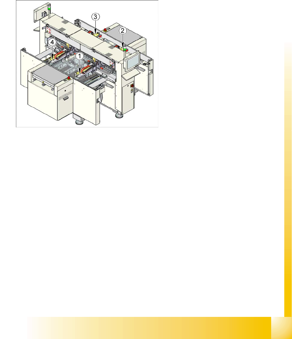
3.2.6 Gantry
3.2.6.1 General
The placement machine is equipped with four gantries. These are used to accurately and independently
position the four C&P heads in the X and Y directions.
Due to their construction, the gantries are resistant to buckling. The precise mechanical guidance of the
axes is achieved with the aid of ball bearing units.
Precise distance measuring systems determine the position of the X and Y axes. This involves the
optoelectronic detection of marker lines on the incremental scales and the transmission of the track
signals to the axis control point in the control unit.
Direct drive techniques are then used to position the placement heads in the X and Y directions. This
prevents the typical frictional loss which occurs when complex drive systems are used. This solution also
avoids the wear and tear which can significantly impair the accuracy of positioning systems over time.
X-axis drive
With the help of a toothed belt, the rotary movement of the X-axis motor is directly converted into a
lengthwise movement of the placement head, in the X-direction.
Y-axis drive
A linear motor moves the placement head lengthwise, in the Y direction.
Legend:
1. Gantry 1
2. Gantry 2
3. Gantry 3
4. Gantry 4