00195193-02 SG D4 FSE en (1).pdf - 第91页
Communication and Control CAN Bus CAN I/O Module (SLIO) - SIPLACE D4 S tudent Guide SIPLACE D4 (FSE) Communication and Control EN 09/2006 90 4.3.6.4 I/O Module, Subdistrib utor (Output s) nc= not connected (Reserve) Term…
Communication and Control
CAN I/O Module (SLIO) - SIPLACE D4 CAN Bus
Student Guide SIPLACE D4 (FSE)
EN 09/2006 Communication and Control
89
IO1 Di18 M_BE-Tisch
"high" if all CO tables are docked and "low" if one or all of the CO tables
is missing.
(X5qb_3)
IO1 Di19 M_NotAusTaste
"high" if one or both emergency STOP buttons (PCB output or input) have
been activated and "low" if both emergency STOP buttons have been
unlocked.
(X5qb_4)
IO1 Di20 M_BeKlappe
"high" if one or more CO table flaps are open.
Attention! only recommended in connection with "old" feeders.
(X5qb_5)
IO1 Di21 (M_Schlüssselschalter)
"high" if the key switch is activated (switch on) and "low" if the key is set
to off.
(X5qb_6)
IO1 Di22 nc (Reserve) (X5qb_7)
IO1 Di23 nc (Reserve) (X5qb_8)
Terminals I / O Description / Note
Communication and Control
CAN Bus CAN I/O Module (SLIO) - SIPLACE D4
Student Guide SIPLACE D4 (FSE)
Communication and Control EN 09/2006
90
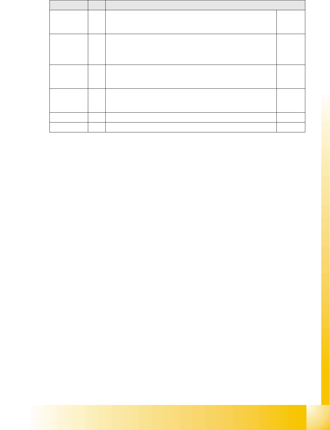
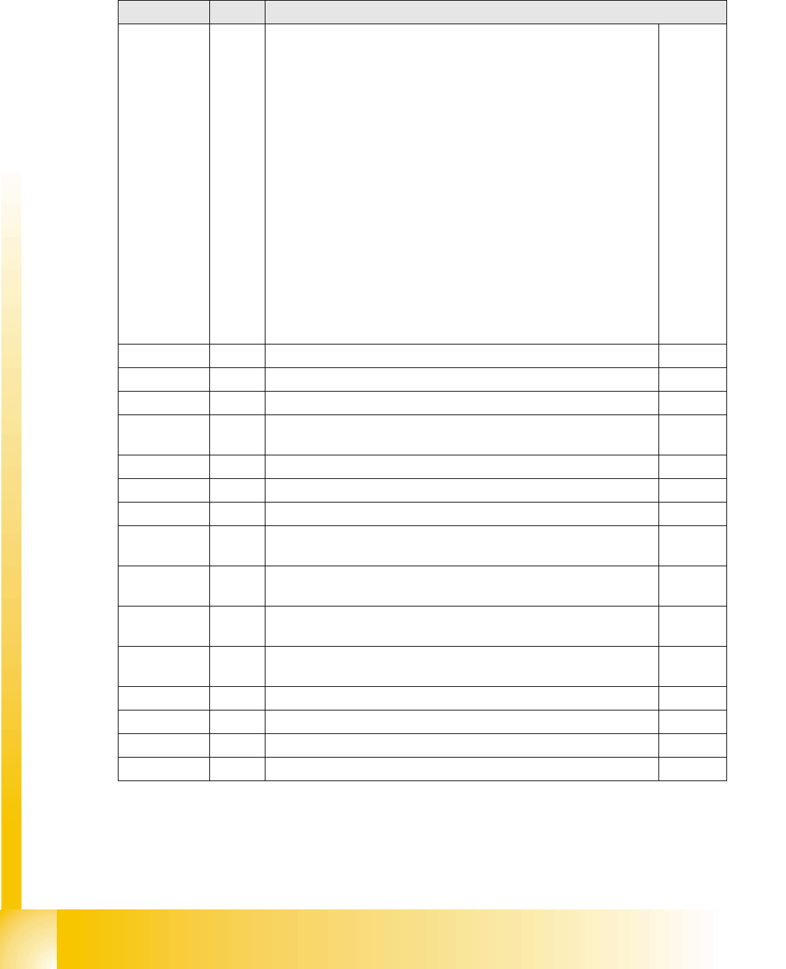
4.3.6.4 I/O Module, Subdistributor (Outputs)
nc= not connected (Reserve)
Terminals I / O Description / Note
IO1 Do0 Software St_Ein or software release
When a "high" signal is permanently supplied to this port (24 V), the
placement machine can be put into operation. The message M_Bereit
switches from "low" to "high" (IO1/Di10), when the auxiliary contactor
K4 contacts have actually switched over. The contacts on this contactor
switch the operating voltage (24 V), the emergency STOP circuit and
the start buttons at the protective contactor combination K6.
Once all 6 hoods are closed, all 4 CO flaps closed, the two emergency
STOP buttons unlocked and all CO trolleys docked into place, the
protective contactor combination can be activated with one of the start
buttons.
The PCC contacts switch the following:
The contactors K2, K3 and K23 are switched on and the
intermediate circuit voltage (somewhat delayed) is supplied to the X,
Y and star servo axis boards.
The operating voltage and the compressed air (valve) are supplied
to the tape cutter.
Two safety loops for sectors 2 and 4.
The operating voltage is switched on for the PCB conveyor motors.
(X7qb_1)
IO1 Do1 nc (Reserve) (X7qb_2)
IO1 Do2 nc (Reserve) (X7qb_3)
IO1 Do3 nc (Reserve) (X7qb_4)
IO1 Do4 St_Bauteilezähler
Each "high" pulse increases the component counter by one.
(X7qb_5)
IO1 Do5 nc (Reserve) (X7qb_6)
IO1 Do6 nc (Reserve) (X7qb_7)
IO1 Do7 nc (Reserve) (X7qb_8)
IO1 Do8 St_VentilPipetten_1a
“high” signal opens the nozzle changer.
(X8qb_1)
IO1 Do9 St_VentilPipetten_1b
“high” signal opens the nozzle changer.
(X8qb_2)
IO1 Do10 St_VentilPipetten_4a
“high” signal opens the nozzle changer.
(X8qb_3)
IO1 Do11 St_VentilPipetten_4b
“high” signal opens the nozzle changer.
(X8qb_4)
IO1 Do12 nc (Reserve) (X8qb_5)
IO1 Do13 nc (Reserve) (X8qb_6)
IO1 Do14 nc (Reserve) (X8qb_7)
IO1 Do15 nc (Reserve) (X8qb_8)
Communication and Control
CAN Bus Communication with Axis Controller CAN Bus
Student Guide SIPLACE D4 (FSE)
EN 09/2006 Communication and Control
91
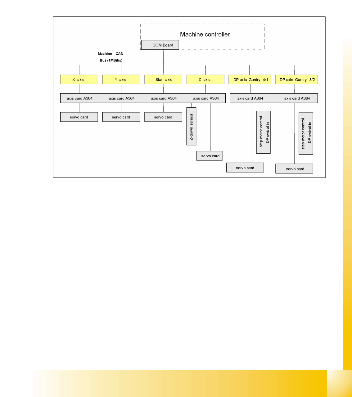
4.3.7 CAN Bus Communication with Axis Controller
In previous Siplace placement machines, the communication and data flow between axis controller and
machine controller was achieved using the SMP bus. From the HF machine generation onwards, the
SMP bus is no longer used with the axis system.
The communication between the axis controller modules is now achieved using the CAN Bus. All the
information exchanged between these modules is transmitted via the CAN bus (e.g. axis parameters,
target position, end position signal ...). This means that the number of individual telegrams increases
significantly over time, compared to the amount of data in older machine generations.
4.3 - 17: Overview axis controller