00195193-02 SG D4 FSE en (1).pdf - 第90页
Communication and Control CAN I/O Module (SLIO) - SIPLACE D4 CAN Bus Student Guide SIPLACE D4 (FSE) EN 09/2006 Communica tion and Control 89 IO1 Di18 M_ BE-Tisch "high" if all CO tables are docked and "low…
Communication and Control
CAN Bus CAN I/O Module (SLIO) - SIPLACE D4
Student Guide SIPLACE D4 (FSE)
Communication and Control EN 09/2006
88
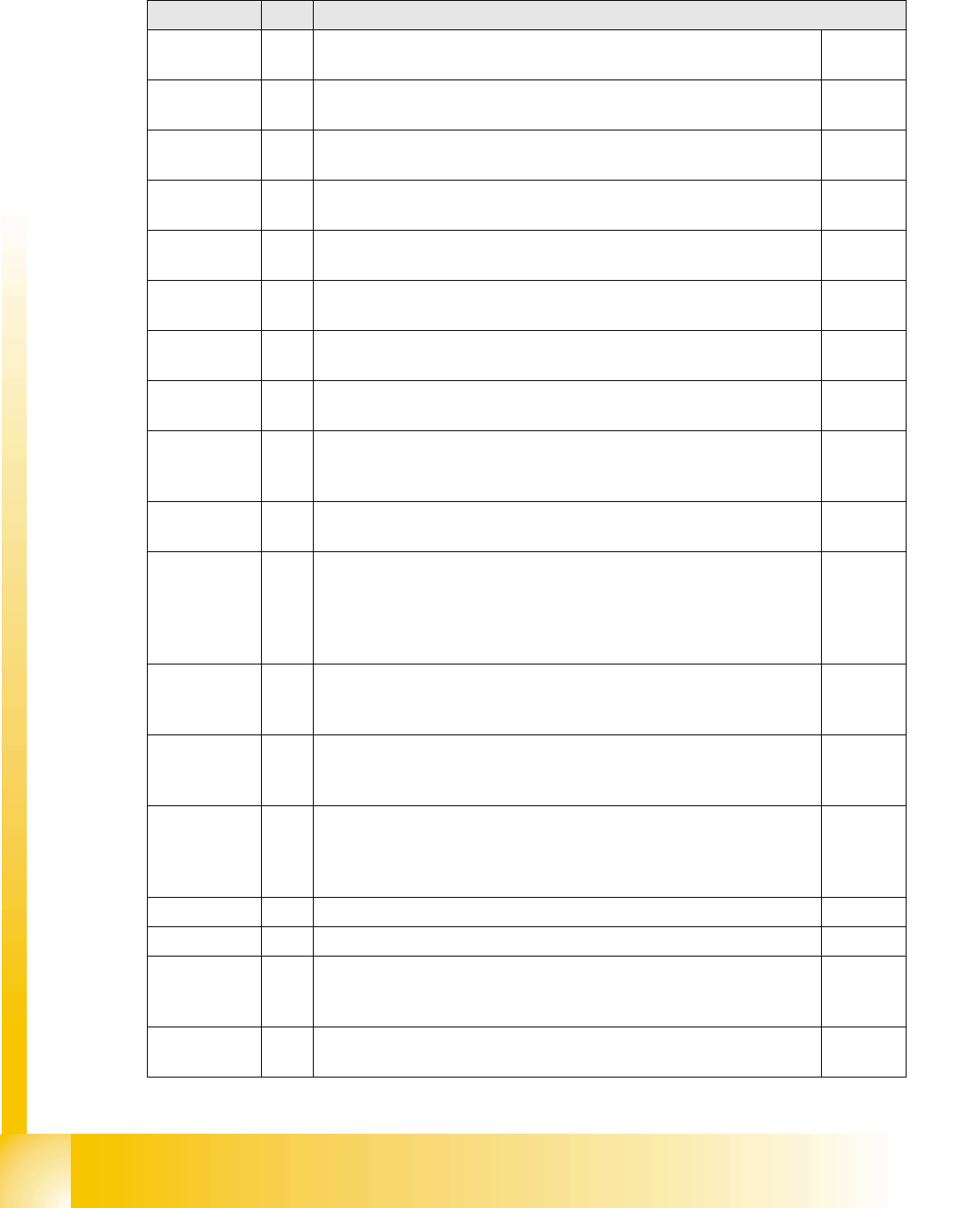
4.3.6.3 I/O Module, Subdistributor (Inputs)
nc= not connected (Reserve)
Terminals I / O Description / Note
IO1 Di0 M_Pip.Links (auf)_1a
"high" if nozzle changer is open
(X3qb_1)
IO1 Di1 M_Pip.Rechts (zu)_1a
"high"if nozzle changer is closed
(X3qb_2)
IO1 Di2 M_Pip.Links (auf)_1b
"high" if nozzle changer is open
(X3qb_3)
IO1 Di3 M_Pip.Rechts (zu)_1b
"high"if nozzle changer is closed
(X3qb_4)
IO1 Di4 M_Pip.Links (auf)_4a
"high" if nozzle changer is open
(X3qb_5)
IO1 Di5 M_Pip.Rechts (zu)_4a
"high"if nozzle changer is closed
(X3qb_6)
IO1 Di6 M_Pip.Links (auf)_4b
"high" if nozzle changer is open
(X3qb_7)
IO1 Di7 M_Pip.Rechts (zu)_4b
"high"if nozzle changer is closed
(X3qb_8)
IO1 Di8 M_StartTaste
"high" while start button is pressed. The function of this button triggers the
protective contactor combination, all axes are ready for operation.
(X4qb_1)
IO1 Di9 M_StopTaste
"high" while stop button is pressed, no hardware consequences.
(X4qb_2)
IO1 Di10 M_Bereit
The telegram M_Bereit switches from "low" to "high" when the power
supply actually supplies operating voltage to the protective contactor
combination PCC (K6) (only possible if St_Ein was previously set to
"high"(contactor K4 switches), this enables the PCC).
(X4qb_3)
IO1 Di11 (M_PortalCrash1/4)
A "low" signal reports that gantries 1 and 4 have come too near! The
"high" signal indicates normal operating status.
(X4qb_4)
IO1 Di12 (M_PortalCrash2/3)
A "low" signal reports that gantries 2 and 3 have come too near! The
"high" signal indicates normal operating status.
(X4qb_5)
IO1 Di13 M_ SteuerungEin or S_ControlOn
A "high" is supplied when the intermediate circuit voltage for the X and Y
servo amplifier is switched through to axis unit 1 and 2 (contactor K23
activated)
(X4qb_6)
IO1 Di14 nc (Reserve) (X4qb_7)
IO1 Di15 nc (Reserve) (X4qb_8)
IO1 Di16 SecurityLoopOK
“high” if the security loop is closed (all hoods and CO flaps are closed, all
emergency STOP buttons are unlocked)
(X5qb_1)
IO1 Di17 M_Haube
"high" if one or more protective hoods are open.
(X5qb_2)
Communication and Control
CAN I/O Module (SLIO) - SIPLACE D4 CAN Bus
Student Guide SIPLACE D4 (FSE)
EN 09/2006 Communication and Control
89
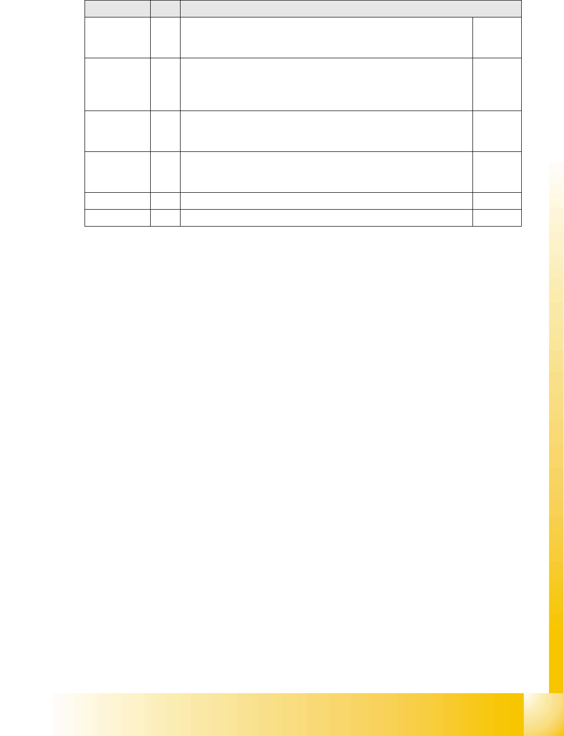
IO1 Di18 M_BE-Tisch
"high" if all CO tables are docked and "low" if one or all of the CO tables
is missing.
(X5qb_3)
IO1 Di19 M_NotAusTaste
"high" if one or both emergency STOP buttons (PCB output or input) have
been activated and "low" if both emergency STOP buttons have been
unlocked.
(X5qb_4)
IO1 Di20 M_BeKlappe
"high" if one or more CO table flaps are open.
Attention! only recommended in connection with "old" feeders.
(X5qb_5)
IO1 Di21 (M_Schlüssselschalter)
"high" if the key switch is activated (switch on) and "low" if the key is set
to off.
(X5qb_6)
IO1 Di22 nc (Reserve) (X5qb_7)
IO1 Di23 nc (Reserve) (X5qb_8)
Terminals I / O Description / Note
Communication and Control
CAN Bus CAN I/O Module (SLIO) - SIPLACE D4
Student Guide SIPLACE D4 (FSE)
Communication and Control EN 09/2006
90
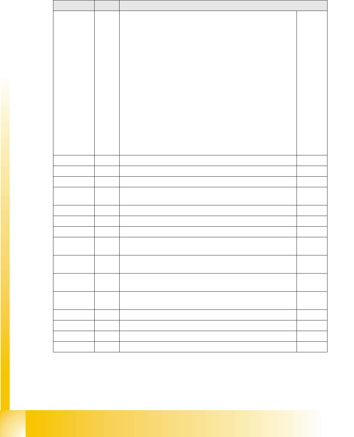
4.3.6.4 I/O Module, Subdistributor (Outputs)
nc= not connected (Reserve)
Terminals I / O Description / Note
IO1 Do0 Software St_Ein or software release
When a "high" signal is permanently supplied to this port (24 V), the
placement machine can be put into operation. The message M_Bereit
switches from "low" to "high" (IO1/Di10), when the auxiliary contactor
K4 contacts have actually switched over. The contacts on this contactor
switch the operating voltage (24 V), the emergency STOP circuit and
the start buttons at the protective contactor combination K6.
Once all 6 hoods are closed, all 4 CO flaps closed, the two emergency
STOP buttons unlocked and all CO trolleys docked into place, the
protective contactor combination can be activated with one of the start
buttons.
The PCC contacts switch the following:
The contactors K2, K3 and K23 are switched on and the
intermediate circuit voltage (somewhat delayed) is supplied to the X,
Y and star servo axis boards.
The operating voltage and the compressed air (valve) are supplied
to the tape cutter.
Two safety loops for sectors 2 and 4.
The operating voltage is switched on for the PCB conveyor motors.
(X7qb_1)
IO1 Do1 nc (Reserve) (X7qb_2)
IO1 Do2 nc (Reserve) (X7qb_3)
IO1 Do3 nc (Reserve) (X7qb_4)
IO1 Do4 St_Bauteilezähler
Each "high" pulse increases the component counter by one.
(X7qb_5)
IO1 Do5 nc (Reserve) (X7qb_6)
IO1 Do6 nc (Reserve) (X7qb_7)
IO1 Do7 nc (Reserve) (X7qb_8)
IO1 Do8 St_VentilPipetten_1a
“high” signal opens the nozzle changer.
(X8qb_1)
IO1 Do9 St_VentilPipetten_1b
“high” signal opens the nozzle changer.
(X8qb_2)
IO1 Do10 St_VentilPipetten_4a
“high” signal opens the nozzle changer.
(X8qb_3)
IO1 Do11 St_VentilPipetten_4b
“high” signal opens the nozzle changer.
(X8qb_4)
IO1 Do12 nc (Reserve) (X8qb_5)
IO1 Do13 nc (Reserve) (X8qb_6)
IO1 Do14 nc (Reserve) (X8qb_7)
IO1 Do15 nc (Reserve) (X8qb_8)