00195193-02 SG D4 FSE en (1).pdf - 第217页
C&P12 Placement Head Placement Procedure Placing Component 7 S tudent Guide SIPLACE D4 (FSE) C&P12 Placement Head EN 09/2006 202 9.2.16 Placing Component 7 9.2.17 Placing Component 12 Star position 180° Vision …
C&P12 Placement Head
Placing Component 1 Placement Procedure
Student Guide SIPLACE D4 (FSE)
EN 09/2006 C&P12 Placement Head
201
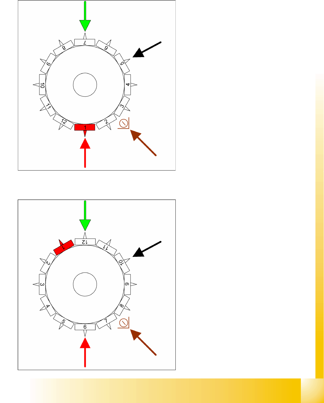
9.2.14 Placing Component 1
9.2.15 Placing Component 6
Star position 0°
Vision system: optical centering of component
7
DP station rotation of component 5 into its
exact placement angle
Pickup and placement station place
component 1
Component sensor during the next star step,
the CO presence/CO height is checked at
segment 3.
This procedure continues for the remaining
nozzles.
Star position 150°
Vision system: optical centering of component
12
DP station rotation of component 10 into its
exact placement angle
Pickup and placement station place
component 6
Component sensor during the next star step,
the CO presence/CO height is checked at
segment 8.
C&P12 Placement Head
Placement Procedure Placing Component 7
Student Guide SIPLACE D4 (FSE)
C&P12 Placement Head EN 09/2006
202
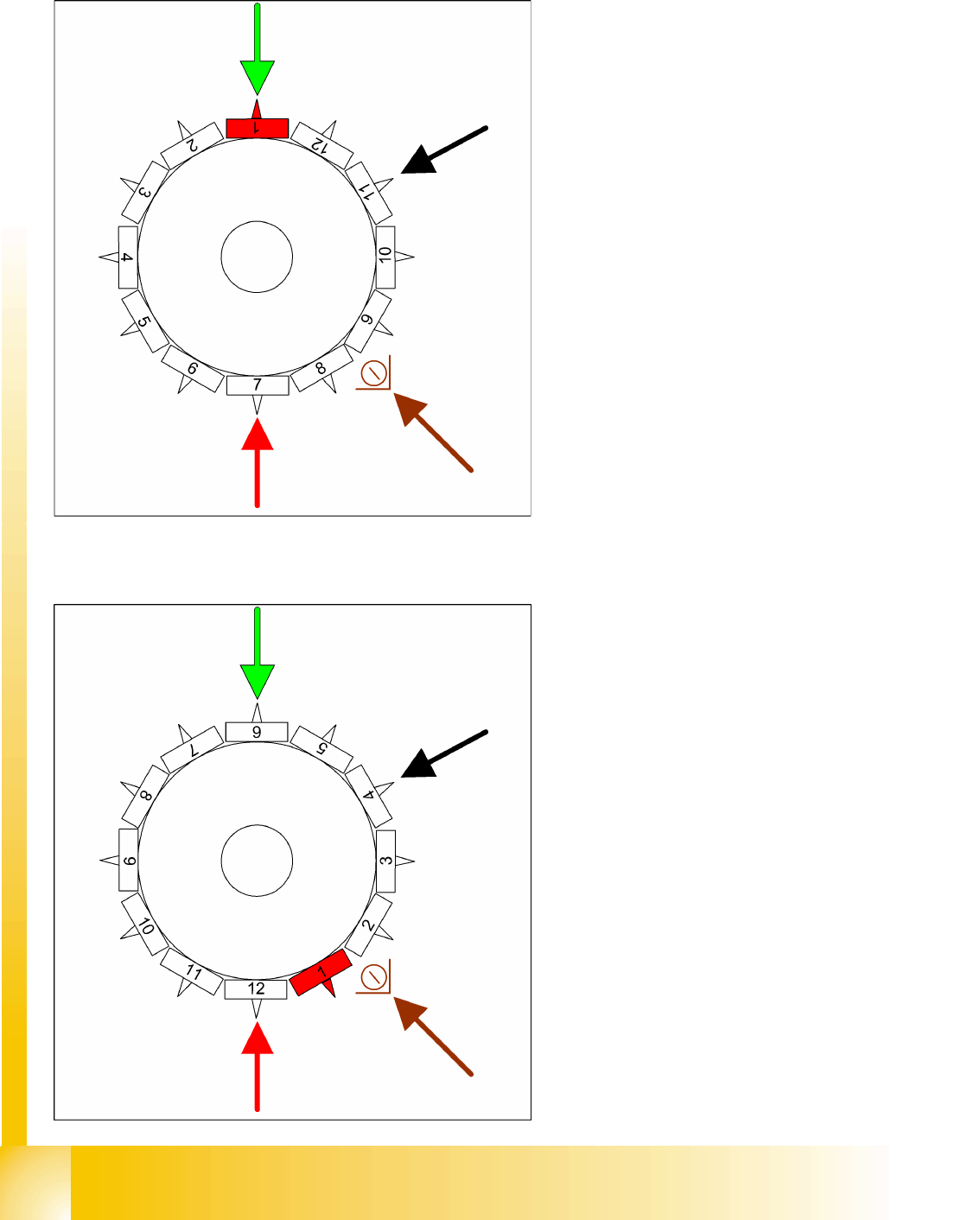
9.2.16 Placing Component 7
9.2.17 Placing Component 12
Star position 180°
Vision system: optical centering of component
1 on other gantry
DP station rotation of component 11 into its
exact placement angle
Pickup and placement station place
component 7
Component sensor option: during the next star
step, the CO presence/CO height is checked
at segment 9.
Star position 330°
Vision system: optical centering of component
6 on other gantry
DP station rotation of nozzle 4 into the pickup
angle for the next placement cycle.
Pickup and placement station place
component 12
Component sensor option: during the next star
step, the nozzle length is measured at
segment 2.

C&P12 Placement Head
Pickup and Placement Cycle For the Next Components Placement Procedure
Student Guide SIPLACE D4 (FSE)
EN 09/2006 C&P12 Placement Head
203
9.2.18 Pickup and Placement Cycle For the Next Components
After all components in the first head cycle have been placed on the board, the gantry axes move
the placement head to the pickup position for the next pickup cycle.
The next pickup cycle is performed for components 13 - 24.
The subsequent pickup cycles are then performed in the same manner. The machine performs
repair runs where necessary.
9.2.19 Segment with a "Defective Component“
If the optical centering of a component (ident error) or the vacuum check before placement (alternatively,
CO recognition before placement) fails, the component will not be placed and will remain on the nozzle.
The turning station will still rotate this nozzle into the pickup angle for the new component , if this
segment is in the rotation position.
If this segment is in the pickup position:
the release procedure will be enabled,
the X/Y axes will move to the reject position for this gantry,
the star will rotate the segment into the reject position,
the component will be released downwards with air kiss
and the new component will be taken up.
The rejected component will then be placed in a repair run after all the other placement cycles for this
placement head have been performed.
9.2.20 Finishing Board Placement
The SIPLACE placement station enables the conveyor system and moves the board to the output
conveyor.
Finally, the SIPLACE placement station reports the number of components used (placed and
rejected) to the line computer.
The OIS (Operator Information System) compiles the placement statistics in relation to the
programmed settings, the programmed utilization and the last reset time. This detailed data is used
to optimize the process.
The machine is now ready for the next board.