00195193-02 SG D4 FSE en (1).pdf - 第86页
Communication and Control CAN I/O Module (SLIO) - SIPLACE D4 CAN Bus Student Guide SIPLACE D4 (FSE) EN 09/2006 Communica tion and Control 85 There is an 8 -fold DIP switch on the I/O modu le. 4.3 - 15: DIP Switch on the …
Communication and Control
CAN Bus CAN I/O Module (SLIO) - SIPLACE D4
Student Guide SIPLACE D4 (FSE)
Communication and Control EN 09/2006
84
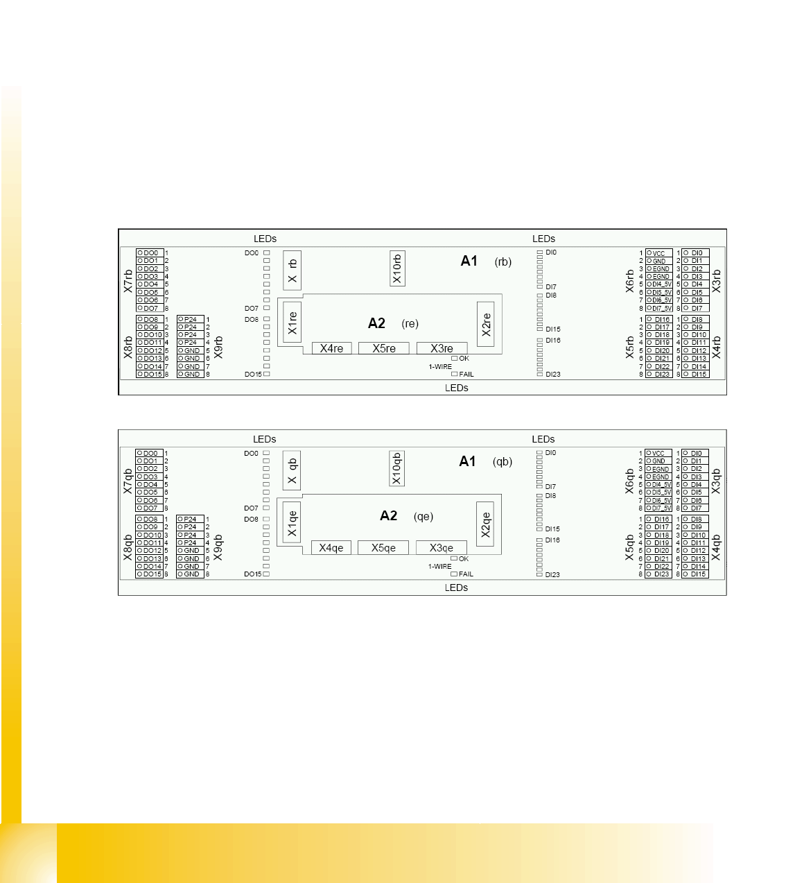
4.3.6 CAN I/O Module (SLIO) - SIPLACE D4
There are 2 CAN Bus I/O modules in the D4 machine. Both modules are absolutely identical and are
located in sectors 2 and 4.
Functions
Micro controller with integrated CAN controller
Data memory
Program memory (flash)
CAN interface with 9 pin connector and address alignment
16 digital Output 24 V with status LED
24 digital Input 24 V with status LED
Download interface
Power supply 5 V and 24 V
Extension on I/O module for the CAN interface (CO tables)
8 digital inputs can be logically linked with the help of a FPGA (freely programmable gate array). The
FPGA is used for incoming security messages.
4.3 - 13: I/O module sector 2
4.3 - 14: I/O module sector 4
Communication and Control
CAN I/O Module (SLIO) - SIPLACE D4 CAN Bus
Student Guide SIPLACE D4 (FSE)
EN 09/2006 Communication and Control
85
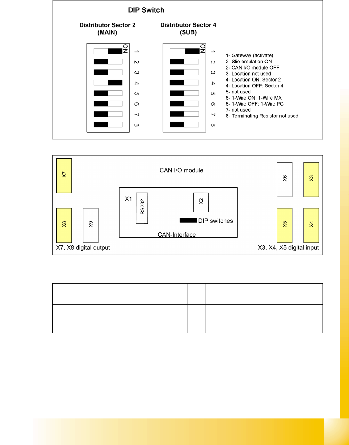
There is an 8-fold DIP switch on the I/O module.
4.3 - 15: DIP Switch on the Main- and Sub Distributor
4.3 - 16: Overview CAN I/O module
Legend
Jumper on the rear side, activates the RS232 interface for service purposes
X1 CAN interface X2 Analog interface, bootstraploader interface
X3, X4, X5 Digital inputs 24V X6 Power supply 5V
X7, X8 Digital outputs 24V X9 Power supply 24V
RS232 Analog interface, bootstraploader
interface
Communication and Control
CAN Bus CAN I/O Module (SLIO) - SIPLACE D4
Student Guide SIPLACE D4 (FSE)
Communication and Control EN 09/2006
86
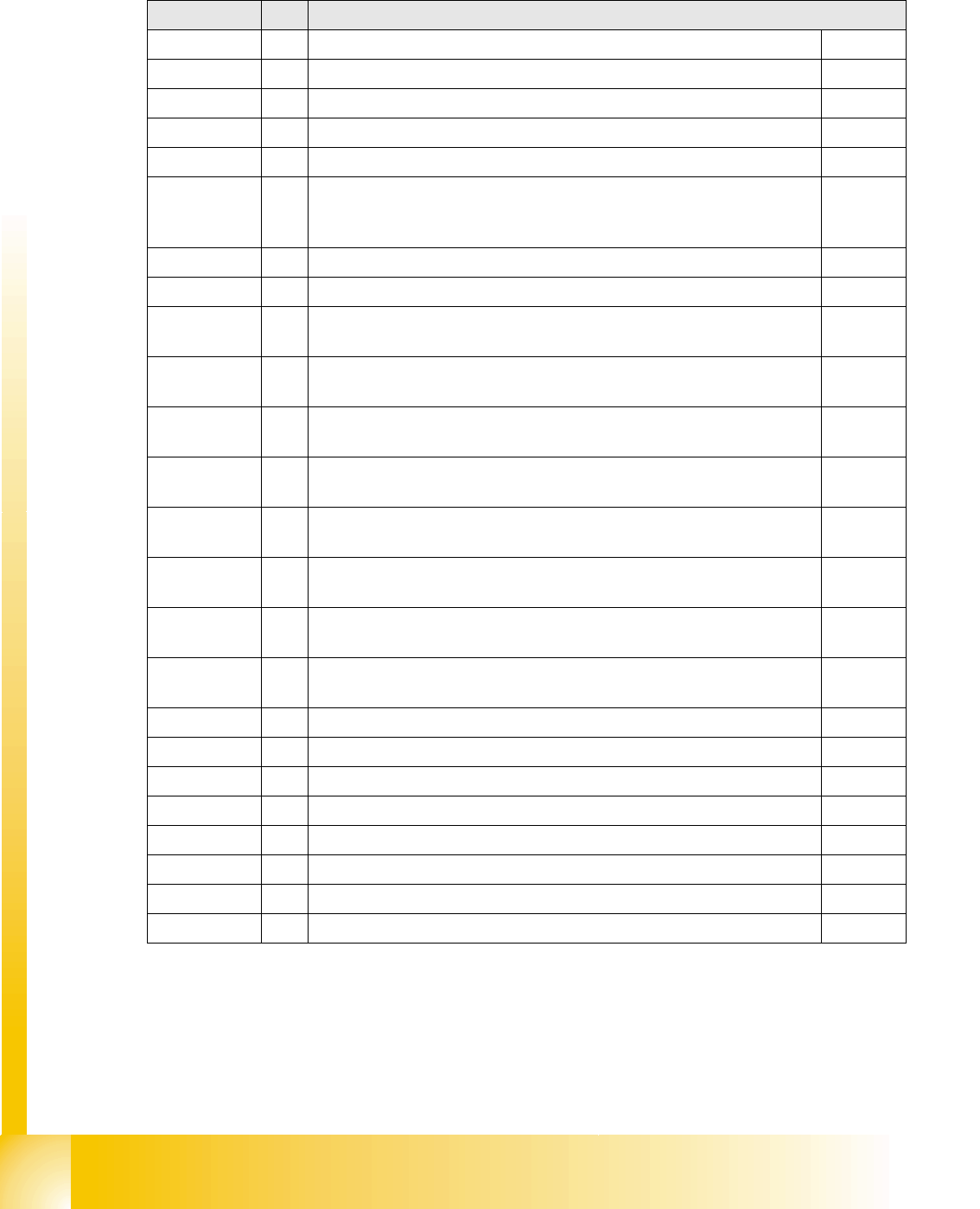
4.3.6.1 I/O module, main distributor (inputs)
nc= not connected (Reserve)
Terminals I / O Description / Note
IO2 Di0 nc (Reserve) (X3rb_1)
IO2 Di1 nc (Reserve) (X3rb_2)
IO2 Di2 nc (Reserve) (X3rb_3)
IO2 Di3 nc (Reserve) (X3rb_4)
IO2 Di4 nc (Reserve) (X3rb_5)
IO2 Di5 M_DruckSensorHauptventil
When the preset air pressure is reached, a "high“ acknowledges the state
"Compressed air level reached“.
(X3rb_6)
IO2 Di6 nc (Reserve) (X3rb_7)
IO2 Di7 nc (Reserve) (X3rb_8)
IO2 Di8 M_Pip.links (auf)_2a
"high“ if nozzle changer is open
(X4rb_1)
IO2 Di9 M_Pip.rechts (zu)_2a
"high“ if nozzle changer is closed
(X4rb_2)
IO2 Di10 M_Pip.links (auf)_2b
"high“ if nozzle changer is open
(X4rb_3)
IO2 Di11 M_Pip.rechts (zu)_2b
"high“ if nozzle changer is closed
(X4rb_4)
IO2 Di12 M_Pip.links (auf)_3a
"high“ if nozzle changer is open
(X4rb_5)
IO2 Di13 M_Pip.rechts (zu)_3a
"high“ if nozzle changer is closed
(X4rb_6)
IO2 Di14 M_Pip.links (auf)_3b
"high“ if nozzle changer is open
(X4rb_7)
IO2 Di15 M_Pip.rechts (zu)_3b
"high“ if nozzle changer is closed
(X4rb_8)
IO2 Di16 nc (Reserve) (X5rb_1)
IO2 Di17 nc (Reserve) (X5rb_2)
IO2 Di18 nc (Reserve) (X5rb_3)
IO2 Di19 nc (Reserve) (X5rb_4)
IO2 Di20 nc (Reserve) (X5rb_5)
IO2 Di21 nc (Reserve) (X5rb_6)
IO2 Di22 nc (Reserve) (X5rb_7)
IO2 Di23 nc (Reserve) (X5rb_8)