00195193-02 SG D4 FSE en (1).pdf - 第47页
Overview Axis Unit and Computer Unit General Overview of Assemblies Student Guide SIPLACE D4 (FSE) EN 09/2006 Overview 47 3.2.2.2.2 Axis controller boards 3.2 - 3: Axis controller boards 3.2.2.2.3 Axis board A3 64 3.2 - …
Overview
General Overview of Assemblies Axis Unit and Computer Unit
Student Guide SIPLACE D4 (FSE)
Overview EN 09/2006
46
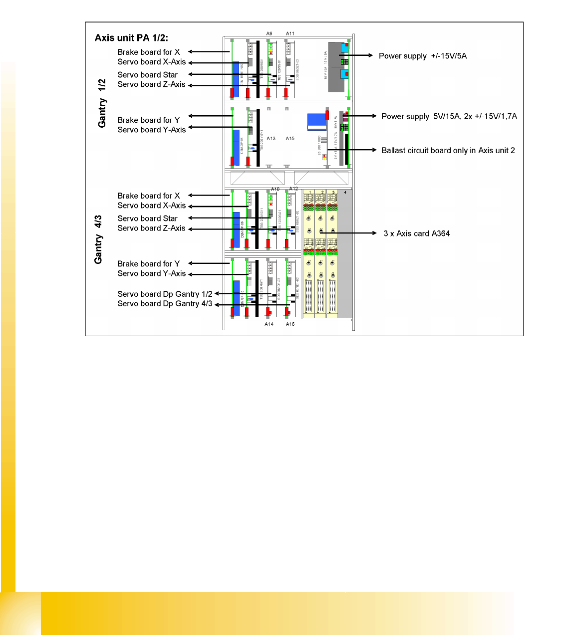
3.2.2.2 Axis Unit
The axis unit contains the servo boards, axis controller boards, power supply (+/-15V,+5V) and the
ballast circuit (only in axis unit 2). The flexible axis unit is equipped with the correct servo and axis boards
for the machine type and head configuration concerned (with C&P12).
Overview of axis unit
D4 machine axis unit in PA1 for gantry 1 and 4 axis units and in PA2 for gantries 2 and 3
3.2.2.2.1 Axis Unit SIPLACE D4
3.2 - 2: D4 axis unit
Overview
Axis Unit and Computer Unit General Overview of Assemblies
Student Guide SIPLACE D4 (FSE)
EN 09/2006 Overview
47
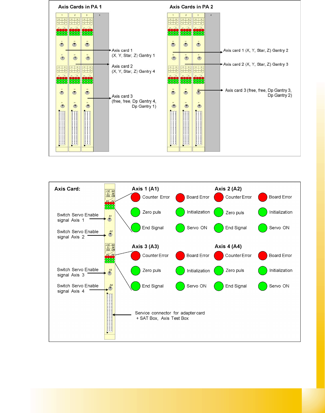
3.2.2.2.2 Axis controller boards
3.2 - 3: Axis controller boards
3.2.2.2.3 Axis board A364
3.2 - 4: D4 axis board
Overview
General Overview of Assemblies Pneumatic Unit
Student Guide SIPLACE D4 (FSE)
Overview EN 09/2006
48
3.2.3 Pneumatic Unit
The pneumatic unit is a fixed installation inside the machine and is located to the right of the middle
section of the machine, behind a flap. The pneumatic unit includes all electrical connections for control/
regulation of the compressed air supply.
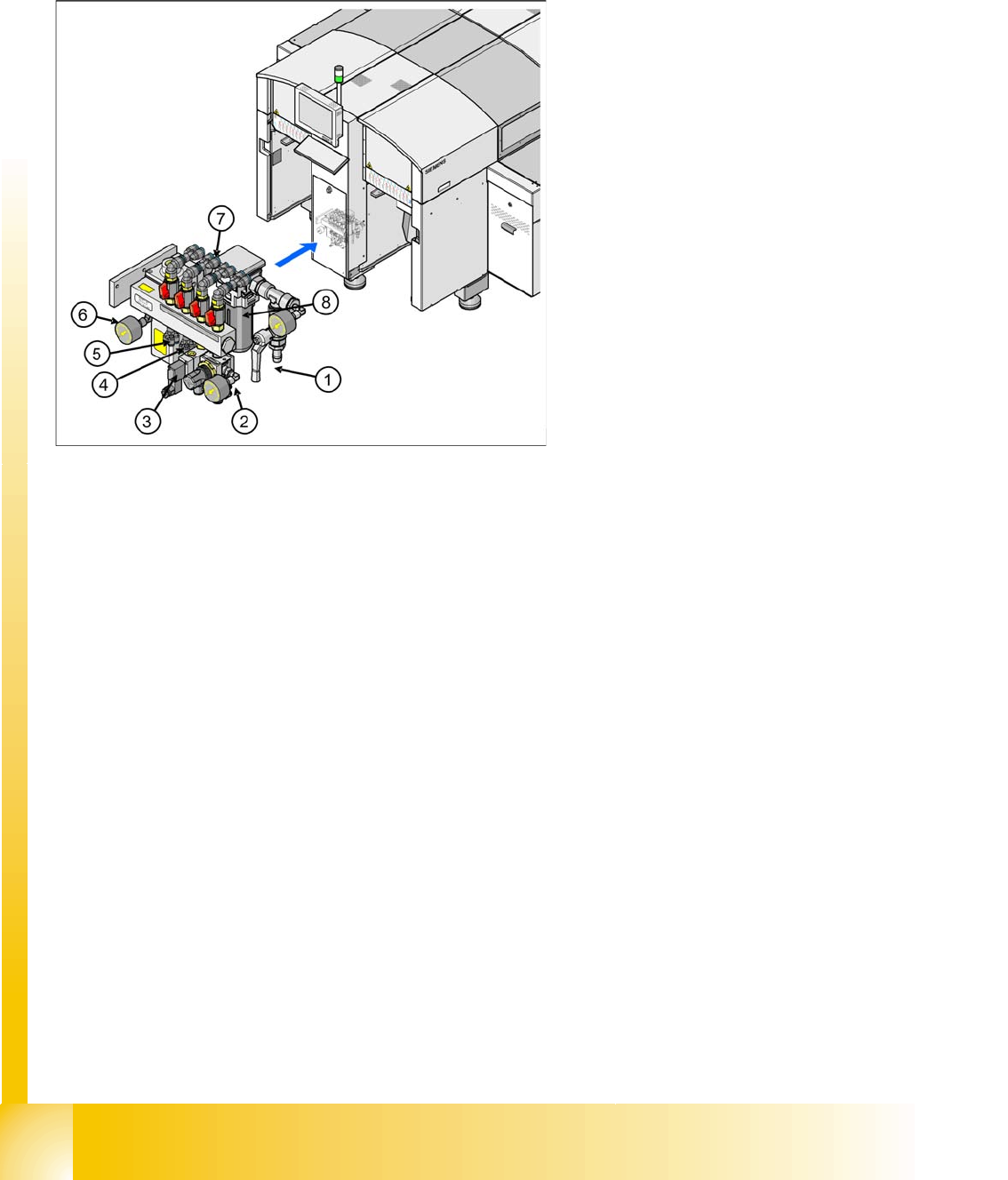
3.2.3.1 Compressed Air Distributor Block
The pneumatic unit is used to prepare and distribute the compressed air required in the machine. The
pressure at the compressed air connection must be at least 4.5 bar.
The following pneumatic circuits are supplied with compressed air via the distributor block:
Gantries 1 - 4 (placement heads), vacuum generation: min. 4.5 bar
Conveyor system: 4.5 bar
Tape cutter for locations 1 - 4: 4.5 bar
Nozzle changer for locations 1 - 4: 4.5 bar
Feed-in units for the changeover tables: 4.5 bar
Bulkcase feeder for locations 1 - 4: 2.5 bar
Fine adjustment for the individual pneumatic circuits is performed directly at the pneumatic units, via the
adjustment valves.
Legend
1. Main compressed air connection with shutoff
valve and manometer
2. 4x connection for bulkcase feeder with
manometer, adjustable (2.5 bar), location 1-4
3. 4x connection for cutters, location 1 - 4
(4.5 bar)
2x connection for conveyor lifting table
4. 4x Connection for nozzle changer (4.5 bar)
5. 4x connection for docking/undocking CO table
(4.5 bar)
6. Electronic control valve for incoming pressure
5.0 bar.
7. 4x connection for gantries 1 - 4, vacuum
generation C&P head with shutoff valves
8. Compressed air filter