00195193-02 SG D4 FSE en (1).pdf - 第200页
Gantry Settings Mechanical adjustment of the incre mental encoder S tudent Guide SIPLACE D4 (FSE) Gantry EN 09/2006 186 8.2.4.2 DIP switch on V ision board Legend DIP Switch 8.2.5 Mechanical adjustment of the incremental…
Gantry
Check the DIP Switches Settings
Student Guide SIPLACE D4 (FSE)
EN 09/2006 Gantry
185
Description of 7-segment display (normal operation "." flashes):
After switch ON the machine appears " 0 " on the display
Display "b" --> BIOS was started.
Display flashes alternatively between "b" and "." --> no application available or unable to start
application.
Display " -I " and " I- " application was loaded.
"." flashes on the display --> ready for operation.
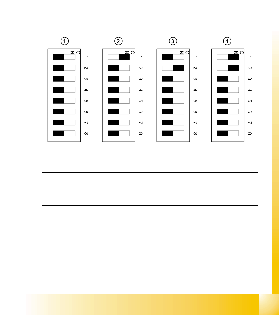
8.2.4 Check the DIP Switches
8.2.4.1 DIP Switch on Gantry Head Distributor
Legend
DIP Switch
1 Gantry 1 3 Gantry 3
2 Gantry 2 4 Gantry 4
1 P0 – gantry ID0 address switch 1 --> gantry 5 Reset - CAN processor 16 Bit (TQM module)
2 P1 – gantry ID1 address switch 2 --> gantry 6 C0 – no current function
3 S1 – switch for DLM head (delay switching on
LB down – Z-axis)
7 C1 – no current function
4 BL – Enable boot loader for serial port 8 S2 – switch for DLM head (no current function)
Gantry
Settings Mechanical adjustment of the incremental encoder
Student Guide SIPLACE D4 (FSE)
Gantry EN 09/2006
186
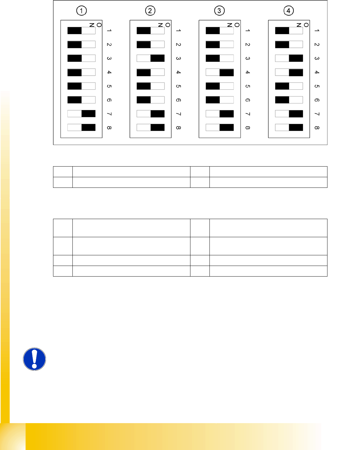
8.2.4.2 DIP switch on Vision board
Legend
DIP Switch
8.2.5 Mechanical adjustment of the incremental encoder
The incremental encoders (read units) on the X and Y axes are mechanically set to a distance of 0.4 mm
+/- 0.1 mm to the incremental scale.
After setting the incremental encoder, you need to check the zero pulse and the track signals (see Sec-
tion 7.4.1 Track signals and Zero pulse [J 149]).
1 Gantry 1 3 Gantry 3
2 Gantry 2 4 Gantry 4
1 Boot mode - CAN processor 16 Bit via
connector X11
5 WPE - Write protect enable (currently
disabled)
2 Reset - CAN processor 16 Bit to subboard 6 CAN R - switch for terminating resistance of
CAN Bus
3 P0 - Gantry address switch 1 7 Test 1 - CAN 1MBit/s ON
4 P1 - Gantry address switch 2 8 Test 0 - CAN IDs --> ON
NOTE:
To set this distance, use one or more small plastic disks with a thickness of
0.4 mm.

Gantry
Mechanical adjustment of the incremental encoder Settings
Student Guide SIPLACE D4 (FSE)
EN 09/2006 Gantry
187