00195193-02 SG D4 FSE en (1).pdf - 第222页
C&P12 Placement Head Z-Axis Down Travel Profile - Pickup Student Guide SIPLACE D4 (FSE) EN 09/2006 C&P12 Placement Head 207 9.3 T ravel Profile - Pickup 9.3.1 Z-Axis Down 9.3.1.1 Det ailed St andard Pickup Proced…

C&P12 Placement Head
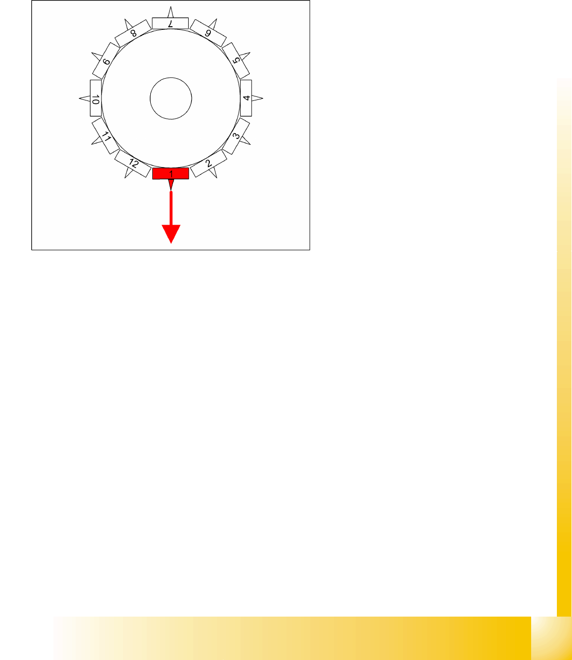
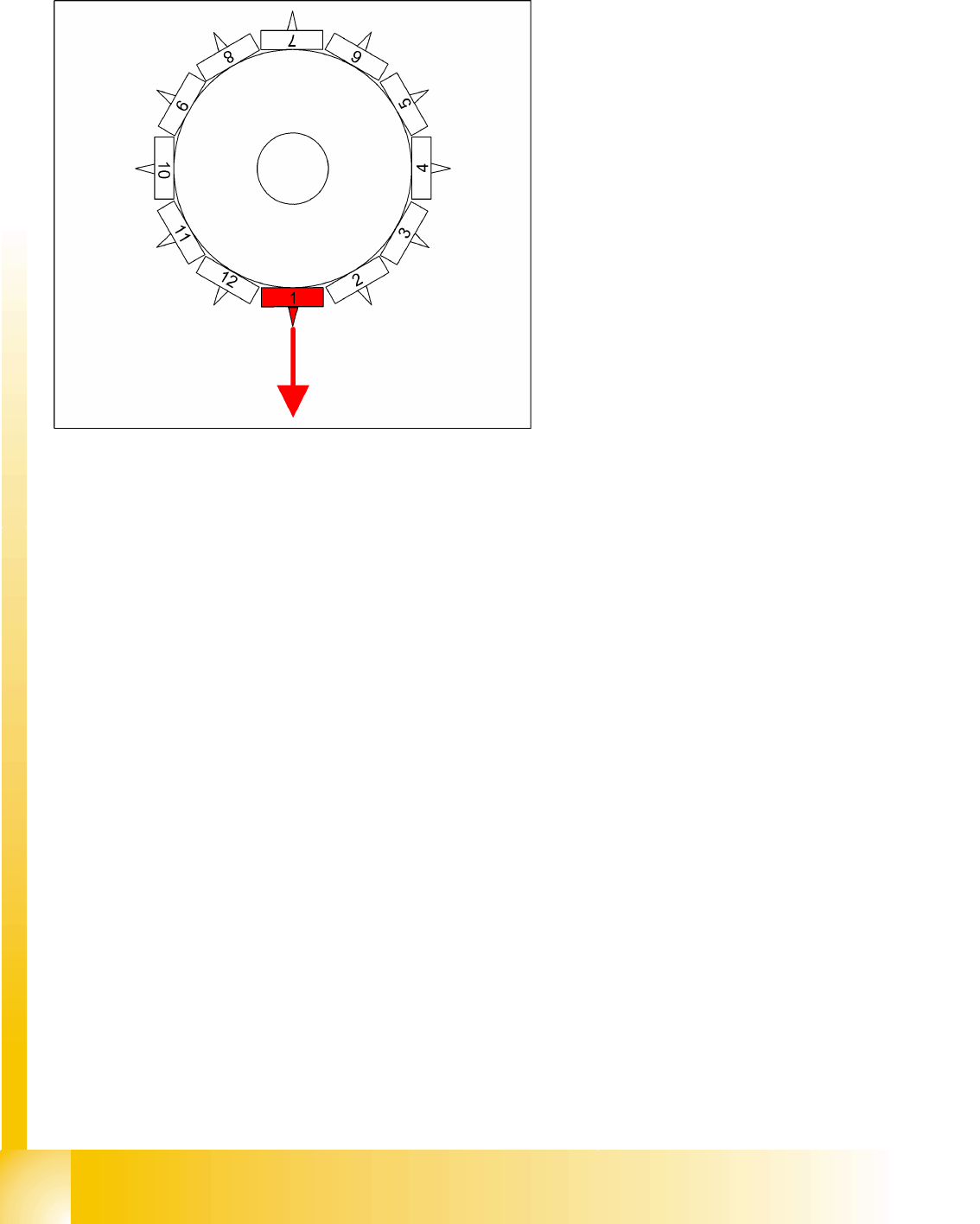
Placement Procedure Optical Nozzle Query
Student Guide SIPLACE D4 (FSE)
C&P12 Placement Head EN 09/2006
206
9.2.25 Optical Nozzle Query
1. After placement of the first board, the nozzle request is enabled:
– All nozzles listed for optical checking will be measured by the CO camera (nozzles such as 901,
904, 911, 914, 925).
– From SW 601, these can be found in the nozzle.lib.xml
– If measurement detects a light point of a defined size and brightness, the machine will issue the
message "nozzle worn down or contaminated".
2. Due to the low component height, small nozzles may touch the soldering paste or adhesive if a
component has slipped.
3. The number of components per segment (number of head cycles), after the next nozzle query has
been performed, should be adjusted to the customer's process requirements. This test is always
performed after board processing has been completed.
4. Another option can also be set:
– Nozzle scanning is not a fatal error and although the machine will show the error, it will not stop.
9.2.26 Air Kiss Control During Placement
This function takes a programming option which was designed for the TWIN and uses it as follows for
the C&P placement head.
Air kiss control during placement
Entering "0" means that the air kiss valve will not be switched on.
(1) Entering "1-50" means that the air kiss valve will be switched off when the stepping motor starts.
(2) Entering "51-150" means that the air kiss valve will be switched off when the stepping motor
rotates by 90°.
(3) Entering "151-255" means that the air kiss valve will be switched off when the light barrier is up
or when the stepping motor rotates by 180°.
No entry "----" (the conversion 501/502 to 503 means switching procedure as in (3) (standard).
Air kiss control for place back (do not reject)
(4) Entry and description as in (1)
(5) Entry and description as in (2)
(6) Entering "151-255" means that the air kiss valve will be switched off when the stepping motor
rotates by 180°.
C&P12 Placement Head
Z-Axis Down Travel Profile - Pickup
Student Guide SIPLACE D4 (FSE)
EN 09/2006 C&P12 Placement Head
207
9.3 Travel Profile - Pickup
9.3.1 Z-Axis Down
9.3.1.1 Detailed Standard Pickup Procedure: Z-Axis Down
Start gantry axes to pickup position of next feeder
and communication with CO table: Start signal to
gantry axes
Start signal X & Y axis to next feeder/this
opens the feeder flap
End position signal for X/Y and star axes:
End position signal for star axis
Enables vacuum query: "segment airtight?"
before pickup
X/Y end position signals available.
Z-axis starts:
Z-axis starts positioning downwards
Light barrier (LB) up switches:
Release signal for function LB down after a
waiting period of approx. 3.6 ms
LB down switches:
End position signal for positioning Z-axis down
and valve positioning drive ON for vacuum.
C&P12 Placement Head
Travel Profile - Pickup Z-Axis Down
Student Guide SIPLACE D4 (FSE)
C&P12 Placement Head EN 09/2006
208
9.3.1.2 Special Mode "Contactless Pickup" Z-Axis Down
Pickup procedure for "contactless pickup":
Start gantry axes to pickup position of feeder and communication with CO table:
– Start signal to gantry axes
– Signal for next feeder / this opens the feeder flap
End position signal for X/Y and star axes:
– End position signal for star axis
– Enables vacuum query: "segment airtight?" before pickup
– X/Y end position signals available.
Z-axis starts with operating mode "positioning type - absolute" to saved nominal height:
– Positioning of Z-axis down
Light barrier (LB) up switches:
– Release for function LB down (although not needed))
Axis controller switches:
– When the taught pickup height is reached, end position signal for Z-axis positioning is issued.
The machine controller switches:
– Valve positioning drive for switching over to vacuum ON.
The positioning procedure for "upwards" is identical to that for standard pickup.
Benefits of special mode "contactless pickup"
The function option "contactless pickup" offers the following benefits:
Prevents touching of CO feeder unit and the possible resulting component shift/jump.
Increases the pickup reliability for small COs, lightweight COs and exotic COs. The nozzle "hovers"
about 0.1 mm above the CO surface. When the vacuum is switched on, the nozzles sucks up the CO
In the case of LRU/LRL 503 and SIPLACE Pro,
contactless pickup can only be programmed in the
CS for SR/MC 503 stations and higher.
When the CO track, for which contactless pickup
has been programmed, is accessed for the first
time, the following is performed:
The Z-axis is taught the pickup height with
increased force. The Z-axis moves until it
mechanically stops.
This pickup height is then reduced by 1.13 mm
(602) to give the nominal height (path of
segment deceleration and ...) and is saved.
The CO used for the teaching procedure is
rejected.