00195193-02 SG D4 FSE en (1).pdf - 第159页
Axis dynamic Axis dynamic basics Servo amplifier TBS .. and SDS ... S tudent Guide SIPLACE D4 (FSE) Axis dynamic EN 09/2006 146 7.3 - 2: Positioning with overshoot into target position During initial positioning into the…
Axis dynamic
Servo amplifier TBS .. and SDS ... Axis dynamic basics
Student Guide SIPLACE D4 (FSE)
EN 09/2006 Axis dynamic
145
7.3 Axis dynamic basics
Each axis starts from a position with acceleration a constant speed phase and deceleration should move
the axis into a target position. The dynamic movement of the axis on the SIPLACE machine is regulated
by a digital control system. A powerful digital processor permanently adjusts the axis behavior to each
state of axis dynamic. This means, that all adjustments for speed (Tacho) and positioning quality (P-gain)
on the servo amplifier are removed. The control signals are different for this new axis control principle.
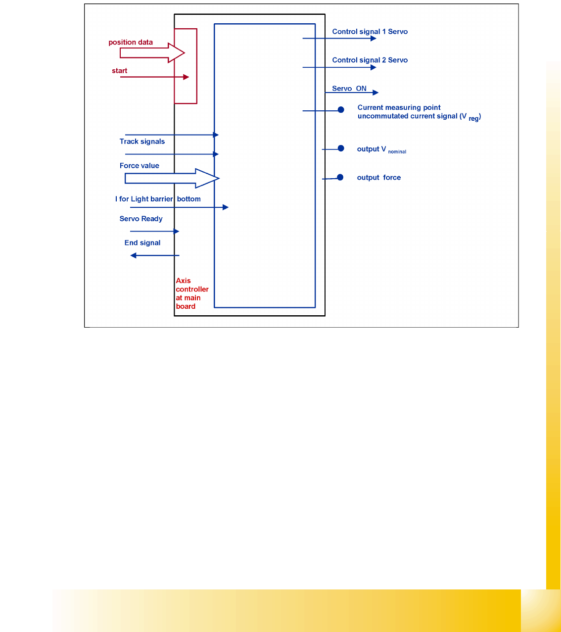
7.3 - 1: Digitally controlled axes for SIPLACE machine
Axis dynamic
Axis dynamic basics Servo amplifier TBS .. and SDS ...
Student Guide SIPLACE D4 (FSE)
Axis dynamic EN 09/2006
146
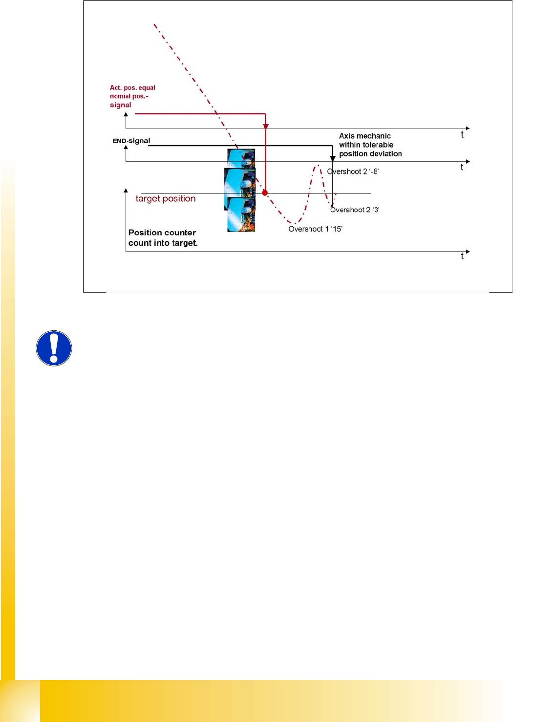
7.3 - 2: Positioning with overshoot into target position
During initial positioning into the target position, the actual equals target position signal triggers an
overshoot count in the axis test box (SAT) for calculation of the position deviation signal.
The known ’V nominal ’ speed signal and the ’force’ force limit signal are replaced by motor phase
nominal current signals to the DC respective AC Drive.
NOTE:
The position deviation signal shows the positioning quality of an axis movement
in position.
Axis dynamic
Servo amplifier TBS .. and SDS ... Axis dynamic basics
Student Guide SIPLACE D4 (FSE)
EN 09/2006 Axis dynamic
147
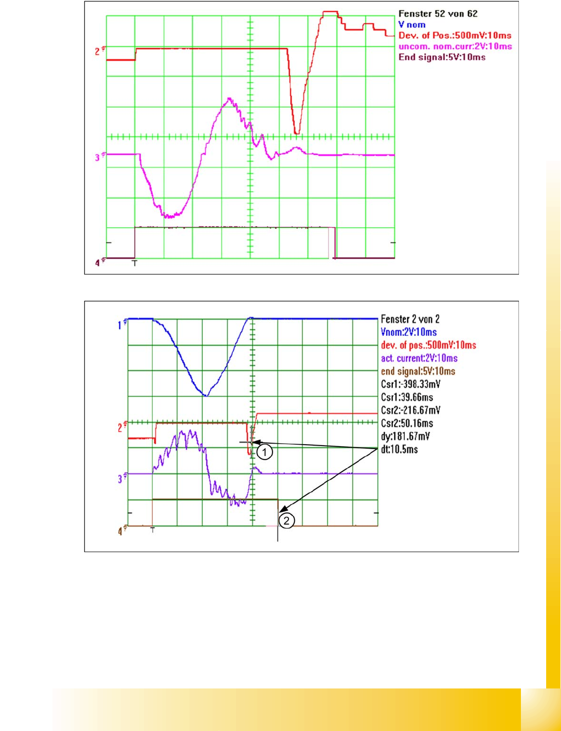
7.3 - 3: The 2nd overshoot sets the end signal
7.3 - 4: Positioning with asymptotic approach after the initial, excessive overshoot
The positioning shown above demonstrates an excessive overshoot. However, no other overshoot
occurs during this positioning process, which could create an end signal. The axis controller has a
’backup strategy’. When the permitted position deviation range is reached, a 10ms timer is started. 10
ms after entering the permissible position deviation range (1) (5 digits) the timer triggers the end signal
(2). The permitted range must not be left during this period.