00195193-02 SG D4 FSE en (1).pdf - 第82页
Communication and Control CAN Bus Structure SIPLACE D4 CAN Bus Student Guide SIPLACE D4 (FSE) EN 09/2006 Communica tion and Control 81 4.3.3 CAN Bus Structure SIPLACE D4 The SIPLACE D4 p lacement mach ine uses a bus sy s…
Communication and Control
CAN Bus CAN Bus protocol
Student Guide SIPLACE D4 (FSE)
Communication and Control EN 09/2006
80
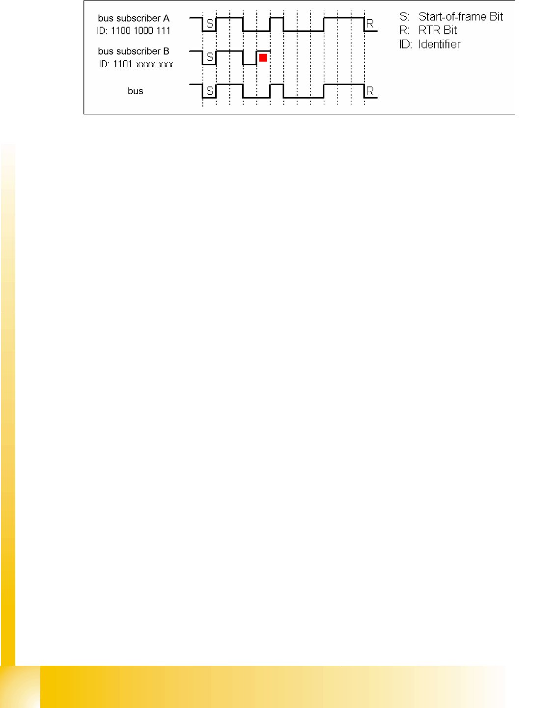
The following example shows arbitration by bit-wise scanning of the identifier by the 2 subscribers.
4.3 - 8: CAN bus arbitration example
If bus subscriber A and B want to transmit, they begin to do so after the start-of-frame bit and compare
in each case the bits sent and received. Since"0" dominates on the bus, bus subscriber B recognizes
that the fourth bit differs from the bits sent and therefore withdraws from the bus until the next start-of-
frame. Bus subscriber A does not recognize a difference and therefore continues to transmit. Messages
with high priority therefore have an identifier which begins with several "0"s.
There are two bus states possible during arbitration: dominant and recessive.
4.3.2.3 Errors on the CAN bus
Error frames
What are error frames?
Error frames are sent by the individual subsystems, if a command does not correspond with the
coding rules or if it has been corrupted i.e. when a CAN telegram has 6 or more consecutive bits with
the same level (high or low).
If a command is recognized by a subscriber, this subscriber immediately informs the other
subscribers and the telegram sender, by issuing an error frame.
Upon receipt of the error frame, all subscribers reject the telegram received and begin to send their
own error frames.
Once the bus is free again, the commend is resent.
If multiple error frames are issued, this indicates that a physical bus error has occurred. If too many
error frames are recognized during operation, a detailed analysis of the CAN signals is required.
Communication and Control
CAN Bus Structure SIPLACE D4 CAN Bus
Student Guide SIPLACE D4 (FSE)
EN 09/2006 Communication and Control
81
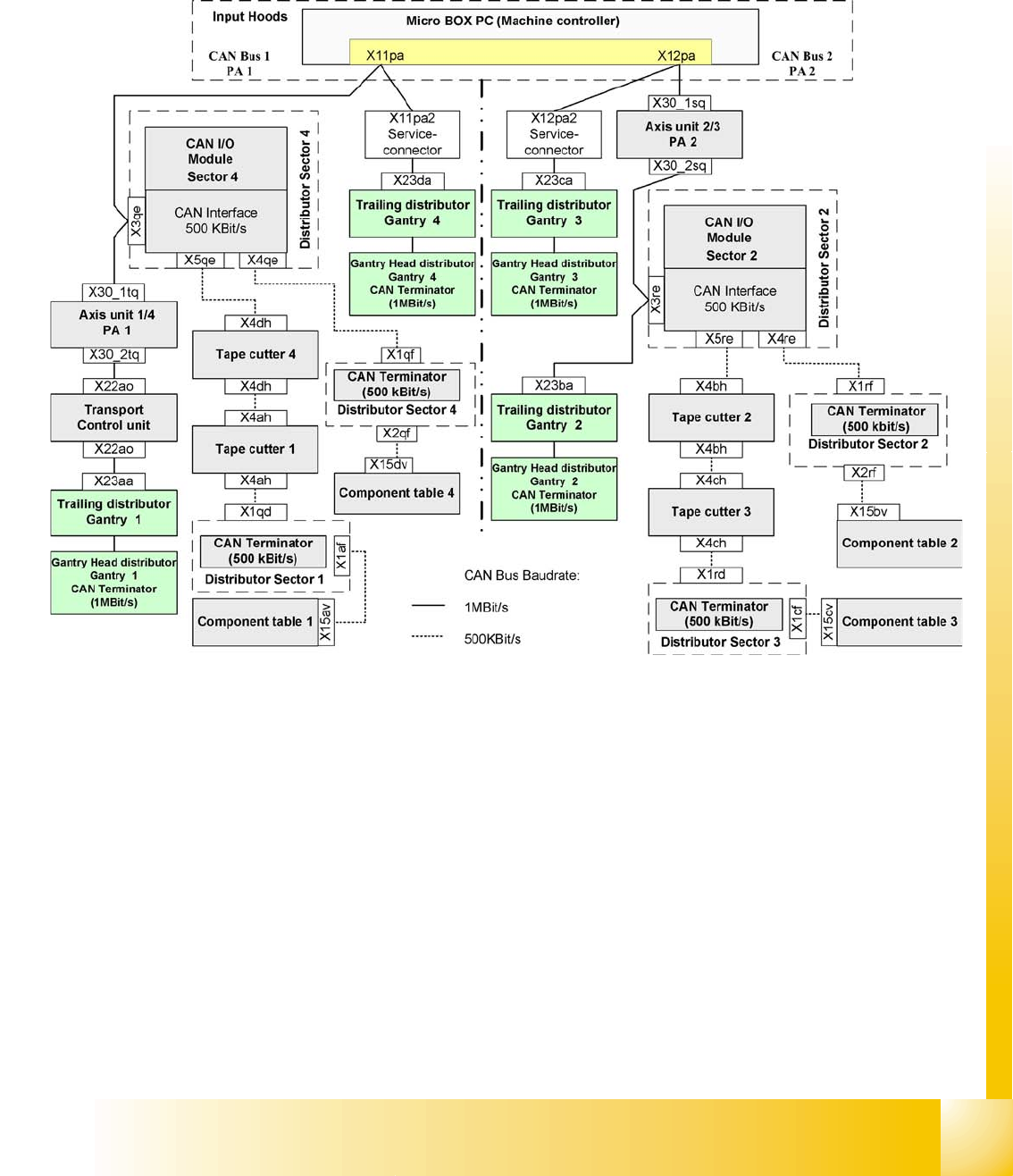
4.3.3 CAN Bus Structure SIPLACE D4
The SIPLACE D4 placement machine uses a bus system with a data transmission rate of 1 MBit/s. The
bus system begins at the communication board and is split in 2 paths. Each path ends with a120 Ohm
terminating resistor at the head board of the respective placement head.
The cutter and the CO table operate with 500 KBit/s , as does the HS60.
4.3 - 9: Overview of CAN bus structure for SIPLACE D4
SMP = Small Micro Processor
Communication and Control
CAN Bus CAN Bus Processor Board C&P Head
Student Guide SIPLACE D4 (FSE)
Communication and Control EN 09/2006
82
4.3.4 CAN Bus Processor Board C&P Head
The TQM 167LC CAN bus processor board is connected to the head board. The processor board is used
at different places in the machine. If the processor board on the head board, the firmware provides at
the processor board the control of the head specific actuators and sensors no matter which head type is
installed.
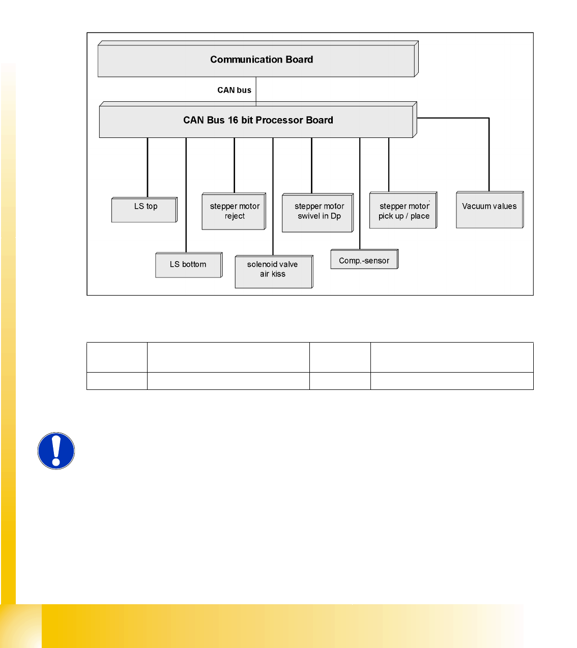
4.3.4.1 CAN BUS-Controlled Functions on the C&P12 Head
The following overview shows various head functions, controlled by the CAN system. Thus, the CAN bus
controls the actuators and sensors of the C&P head.
4.3 - 10: CAN function on C&P head
Legend
LB Light barrier Component
sensor
Component sensor
SM Stepping motor
NOTE:
The status of the 16 Bit PROCESSOR BOARD is indicated on the 7-segment
display.
Normal status on the display is: Display shows slowly flashed " . (for
description see Section C&P12).