00195193-02 SG D4 FSE en (1).pdf - 第189页
Gantry Mechanical Structure of X and Y Axes Overview Student Guide SIPLACE D4 (FSE) EN 09/2006 Gantry 175 8.1 - 3: Mechanical structure of gantries – part 2 -view from below Legend X axis With the help of a toothed belt …
Gantry
Overview Mechanical Structure of X and Y Axes
Student Guide SIPLACE D4 (FSE)
Gantry EN 09/2006
174
8.1.1 Mechanical Structure of X and Y Axes
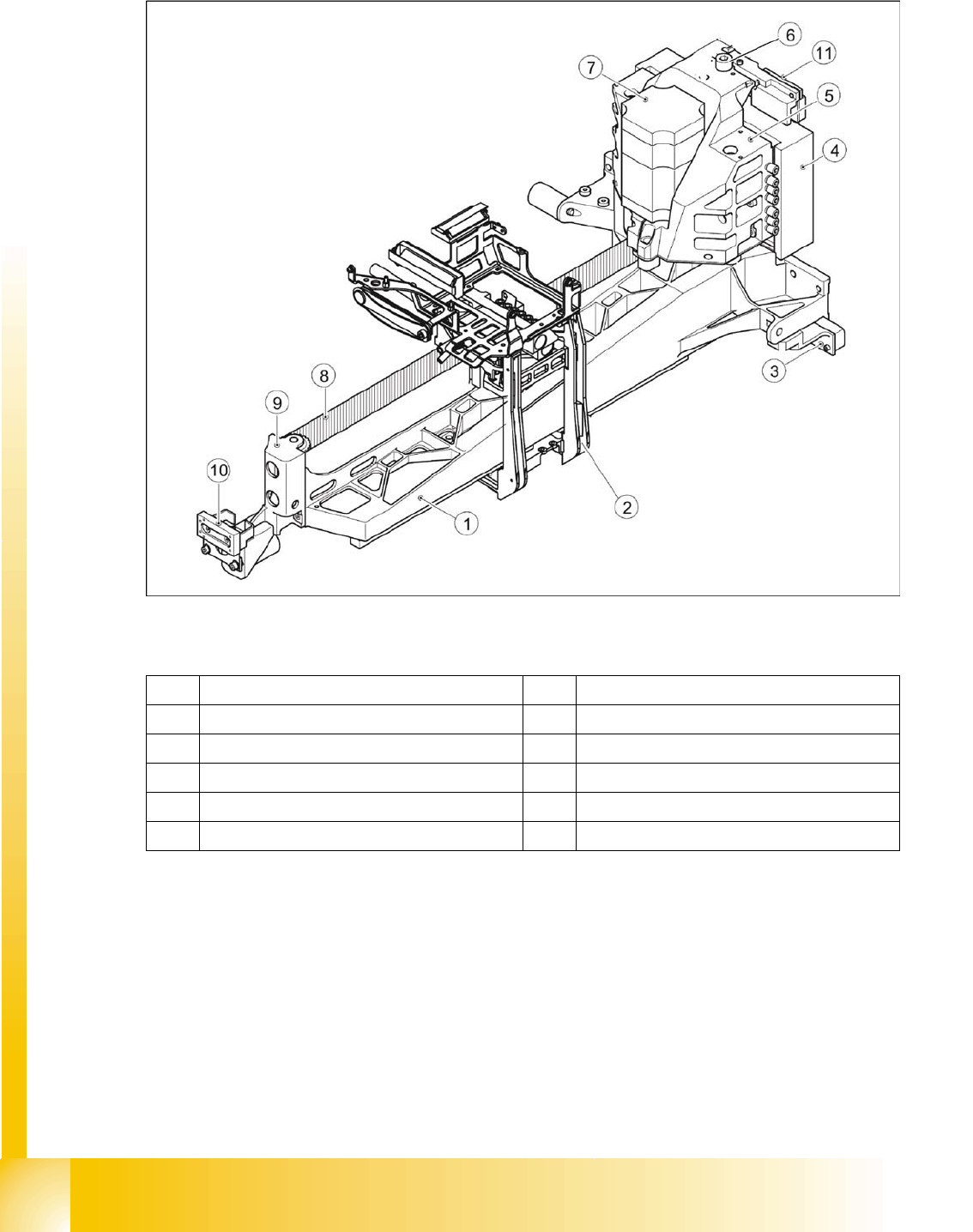
8.1 - 2: Mechanical structure of gantries – part 1
Legend
1 Precision-cast gantry 7 X motor unit
2 Head mount 8 Toothed belt
3 Read unit for Y-axis incremental scale 9 Deflection unit
4 Primary part Y-linear motor 10 Y-axis brake, external
5 Motor bracket 11 Y-axis brake, internal
6 Thrust bearing
Gantry
Mechanical Structure of X and Y Axes Overview
Student Guide SIPLACE D4 (FSE)
EN 09/2006 Gantry
175
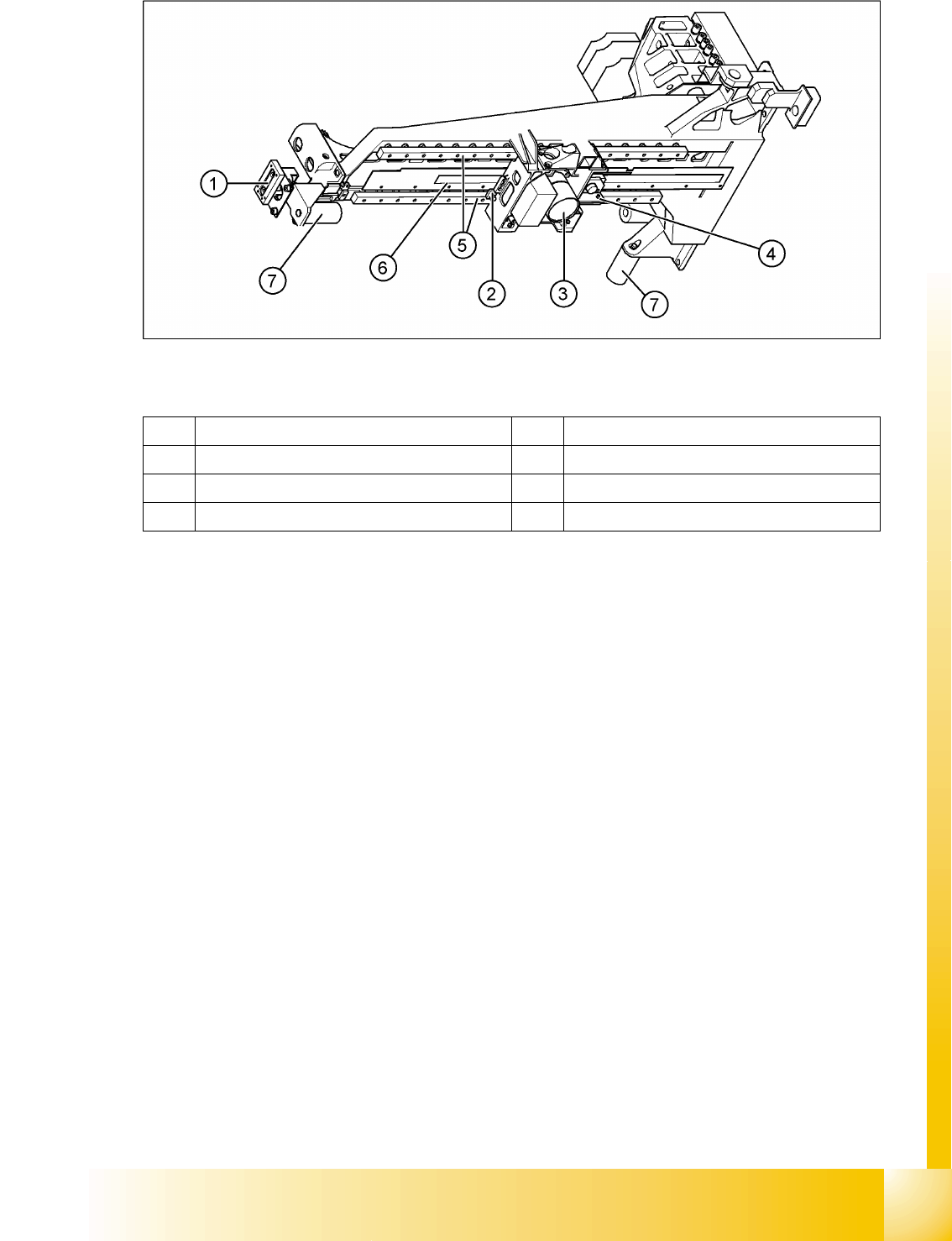
8.1 - 3: Mechanical structure of gantries – part 2 -view from below
Legend
X axis
With the help of a toothed belt drive, the rotary movement of the X-axis motor is directly converted into
a lengthwise movement of the placement head, in the X-direction.
The linear guide rails under the X-axis guide the head assembly plate and the placement head along the
X-axis.
The X-motor is cooled by a fan at the Y-axis pickup position and the motor temperature is also monitored
by a sensor.
Y axis
A linear motor positions the entire gantry (X-axis, head assembly plate and placement head) in the Y-
axis direction. This linear motor consists of a primary and secondary part. The secondary part consists
of permanent magnets, which are fastened lengthwise (Y direction) to the machine frame.
The primary part consists of inductors (motor windings), which are directly fastened to the gantry, in a
casing.
Determining the position
To accurately position the axes, the machine uses incremental scales (metal), which are attached
between the linear guide rails (X-axis or under the secondary part, by the Y-axis).
A corresponding incremental encoder reads the increments from the incremental scales and generates
track signals as a result. The encoder transmits the track signals to the axis control card, which uses the
track signals to determine axis position and to control the motor.
1 Y-axis brake 5 2x linear guide rails, each with a linear bearing
2 X-axis brake 6 X-axis incremental scale
3 Digital PCB camera with optical system 7 Elastomer spring 25x10.5x50
4 X axis read unit
Gantry
Overview Pneumatic connectors on the gantry
Student Guide SIPLACE D4 (FSE)
Gantry EN 09/2006
176
Monitoring the position
Monitoring the track signals (counter edge spacing)
Monitoring the position to the hardware end switches, in accordance with the speed)
Monitoring the two Y axes in one placement area
Additionally each axis has a mechanical end stop (elastomer bumper).
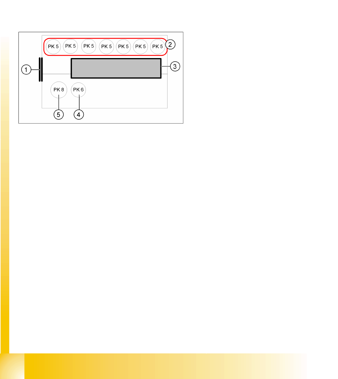
8.1.2 Pneumatic connectors on the gantry
The placement head is supplied with 4.5 bar compressed air from the pneumatic unit. The 7-fold
pneumatic hose is also used to cool the Y-axis motor. The X-axis motor is cooled by the traverse fan.
Legend:
1. Input: Discharged air Venturi nozzle
pneumatic hose (PK12)
2. Input: 7-fold pneumatic hose (PK 5)
3. Silencer for discharged air
4. Compressed air for the pickup / placement
circuit
5. Compressed air for the hold circuit