00195193-02 SG D4 FSE en (1).pdf - 第280页
Modular conveyor Conveyor Settings Move fixed conveyor side for ’conveyor - excess width’ S tudent Guide SIPLACE D4 (FSE) Modular conveyor EN 09/2006 264 1 1.3.3 Move fixed conveyor side for ’conveyor - excess wid th’ Th…
Modular conveyor
Setting the fixed conveyor side (single and dual conveyor) Conveyor Settings
Student Guide SIPLACE D4 (FSE)
EN 09/2006 Modular conveyor
263
11.3.2.2 Connecting the Dual Conveyor Lifting Tables
X Remove the lifting table plate on conveyor lane 2 in PA1 and on lane 1 in PA2.
X Loosen the lockscrew(s) (4) and use a screwdriver to push the hexagonal circlip over the shaft on
lifting table 1.
X Do this for lifting tables in all placement areas. (lifting tables in the PA’s 180° turned.)
X Configure the new conveyor mode in SIPLACE Pro
11.3.2.3 Converting the Single Conveyor Mode Back to Flexible Dual Conveyor Mode
X Select the SITEST conveyor menu "Option and configuration" and then click on
Widen conveyor
to set the standard conveyor mode.
X The flexible conveyor side of conveyor 1 (right side fixed (track 1 left side fix)) is moved to a small
conveyor width.
X The SITEST SW ask to disconnect the lifting tables - Do so-.
X The SITEST SW will now use the conveyor control SW to move the fixed side of conveyor 2 (right
side is fixed (lane 1 left side fixed)) back to its standard position. Check the distances between the
two fixed conveyor lanes. (see Section 11.4.2.1 Widening the Conveyor (Flexible Dual Conveyor for
Single Conveyor Mode) [J 268]).
X Now adjust conveyor width of both tracks to desired values.
NOTE:
This option is only a mechanical function when you use the dual conveyor as
an single conveyor. The two lifting tables move parallel when they are
connected.
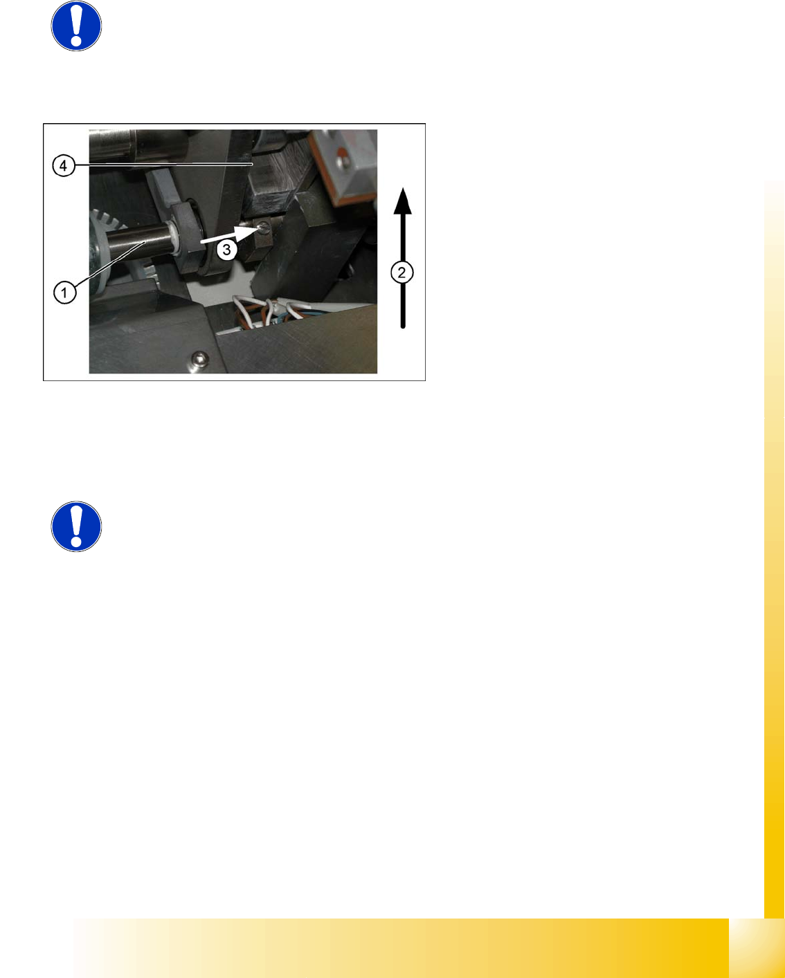
The drive shaft (1) is connected to the piston
rod of the pneumatic cylinder. This shaft
couple the second lifting table of the dual
conveyor. The lifting table drive shaft also has
an additional rod with a hexagonal circlip.
They secure the sleeve shaft in the desired
position.
Direction of transport (2)
Direction (3) in which the hollow shaft from
lifting table 2 (1 in PA 2) is to be moved to lifting
table 1 (2 in PA 2).
Lock screws (4)
NOTE:
When converting the dual conveyor to a single conveyor (flexible dual conveyor,
connect the lifting tables when requested to do so by SITEST (we recommend
doing this without compressed air supply to the lifting table).
This function is supported by SIPLACE Pro.

Modular conveyor
Conveyor Settings Move fixed conveyor side for ’conveyor - excess width’
Student Guide SIPLACE D4 (FSE)
Modular conveyor EN 09/2006
264
11.3.3 Move fixed conveyor side for ’conveyor - excess width’
The standard positions of the fixed conveyor sides are preset.
X Select
Option and configuration
from the SITEST conveyor menu and then click on
Conveyor excess width,
to set the conveyor mode "excess width".
X The fixed conveyor side of conveyor 2 (right side fixed (track 1 left side fix)) remain at its position
X The ’fixed conveyor of track 1(right side fixed (track 2 left side fix)) is moved 34mm outside. This
allow the wider boards. The flexible conveyor side on lane 2 (lane 1 left fixed) can now be set to
accommodate boards which are wider than 216 mm (242 mm).
NOTE:
This operating mode is possible for D machines with single or dual conveyors.
ATTENTION:
After the conversion process, you need to measure/calibrate the board
reference corner and the conveyor sides and then save this information in the
machine data.
Modular conveyor
Checking the limit switch position Conveyor Settings
Student Guide SIPLACE D4 (FSE)
EN 09/2006 Modular conveyor
265
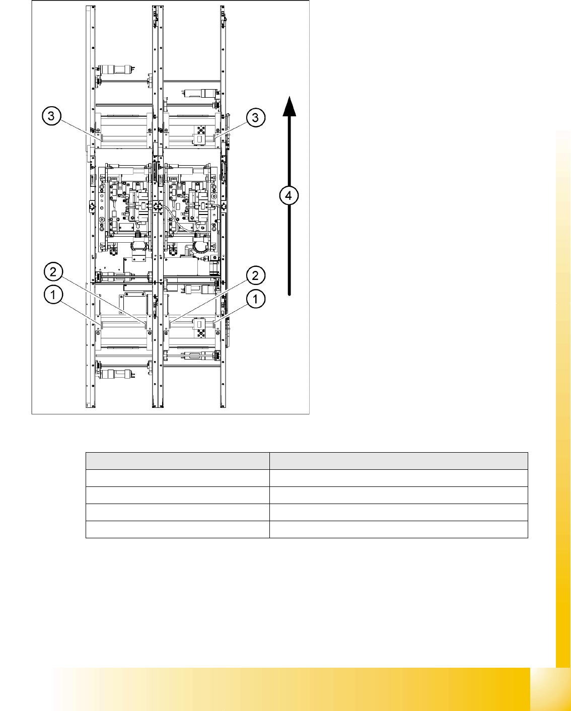
11.3.4 Checking the limit switch position
X Check the minimum and maximum width and ensure that the conveyor sides are parallel.
Legend:
1. Limit switch on the input conveyor - fitted
below the conveyor side
2. Limit switch on the input conveyor - fitted
below the conveyor side
3. Limit switch for the width adjustment unit
4. Transport direction
Limit switches on the input conveyor:
There are 5 limit switches below the conveyor
sides near the input conveyor. The limit switch
is designed to prevent the conveyor sides
hitting one another or the conveyor frame.
Limit switches on the output conveyor:
There are 2 limit switches for the driver near
the output conveyor. They serve to protect the
traveling range and initialize (right side) the
driver for the width adjustment.
Setup Value
Minimum width: 49.7 mm
Maximum width of single conveyor 508.5 mm
Maximum width of dual conveyor 216.5 mm (standard)
Maximum width of dual conveyor 242.5 mm (standard)
Adjustments