00195193-02 SG D4 FSE en (1).pdf - 第138页
Services to the machine Safety and Signaling Circuit Power Supply Unit Student Guide SIPLACE D4 (FSE) EN 09/2006 Services to the machine 131 6.2.14.2.6 Emergency St op Button Control Circuit 6.2 - 11: Emergency stop butt…
Services to the machine
Power Supply Unit Safety and Signaling Circuit
Student Guide SIPLACE D4 (FSE)
Services to the machine EN 09/2006
130
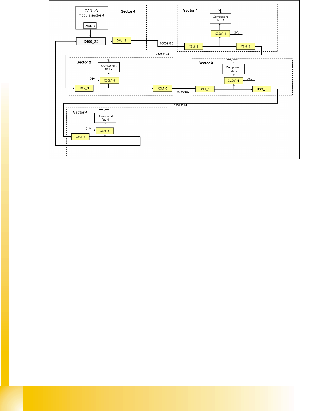
6.2.14.2.5 Feeder Cover Flap Control Circuit
6.2 - 10: Feeder cover flap control circuit
The feeder cover flap circuit consists of 4 contacts, which are switched in parallel mode. If one or more
feeder cover flaps are open, the contact will close and 24 V will be present at the input of the CAN I/O
module in sector 4. This indicates that one of the feeder cover flaps has been opened.
Services to the machine
Safety and Signaling Circuit Power Supply Unit
Student Guide SIPLACE D4 (FSE)
EN 09/2006 Services to the machine
131
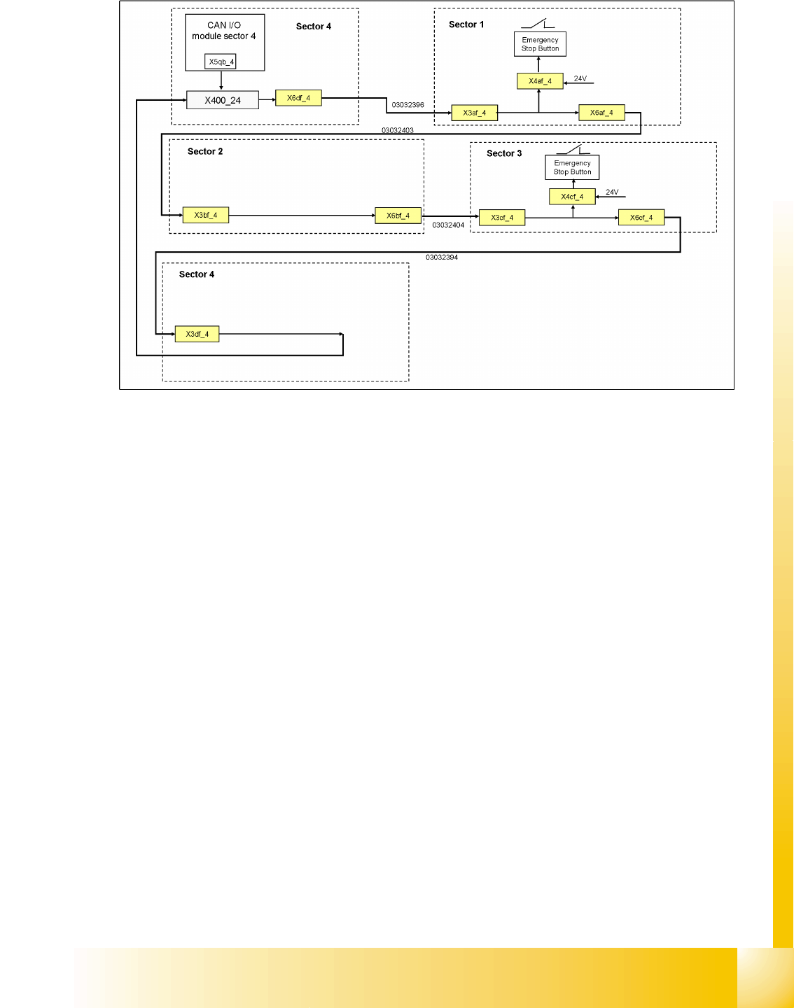
6.2.14.2.6 Emergency Stop Button Control Circuit
6.2 - 11: Emergency stop button control circuit
The emergency stop button circuit consists of 2 contacts, which are switched in parallel mode. If one or
more emergency stop buttons are closed (pressed), the contact will close and 24 V will be present at the
input of the CAN I/O module in sector 4. This will be shown on the station software interface.
If both emergency stop buttons are open (not pressed), 0 V will be present at the input of the CAN I/O
module.

Services to the machine
Power Supply Unit Safety and Signaling Circuit
Student Guide SIPLACE D4 (FSE)
Services to the machine EN 09/2006
132
6.2.14.2.7 How Does the Emergency Stop Circuit Work?
The SIPLACE placement machine can not be used for placement until all the relevant supply voltages
and safety devices have been released by the protective contactor combination.
The following conditions must be fulfilled:
All four component change-over tables must be docked.
All covers must be closed.
Both emergency stop pushbuttons must be released.
The minimum air pressure must be present.
The software release signal must be present when the start button is pressed (CAN I(/O output
x7qb_1)
The message
Safety loop OK
must be issued (CAN I/O output x5qb_1)
24 V must be present at the start button.
After pressing the start button, the protective contactor combination releases the following voltages:
Secondary circuit 200 VDC for X/Y axis servo (via SZ2, SZ3, SZ23).
Secondary circuit 150 V for star axis.
The servo unit receives
the servo release signal
for the servo amplifier. (SZ23)
The message
Ready
must be issued to the CAN I/O module (x4qb_3).
40 V operating voltage for the transport handling.
24 V operating voltage for the tape cutter.
Control ON for axis unit SZ23
Servo enable SZ23