00195193-02 SG D4 FSE en (1).pdf - 第167页
Axis dynamic Axis control gantry Track signals and Zero pulse S tudent Guide SIPLACE D4 (FSE) Axis dynamic EN 09/2006 154 7.4.1.2 Check the track signals 7.4.1.2.3 Analog track signals To check the track signals, connect…
Axis dynamic
Track signals and Zero pulse Axis control gantry
Student Guide SIPLACE D4 (FSE)
EN 09/2006 Axis dynamic
153
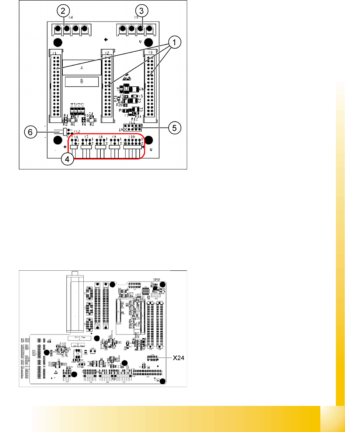
X11 on Y-axis gantry interface
X24 on X-Axis Gantry Head Distributor
Legend:
1. X1/X2/X3 flat ribbon cable
2. X4 motor Y-axis (U,V,W)
3. X5 motor X-axis (U,V,W)
4. X6 X-motor temperature sensor
X7 end position proximity switch for Y-axis (not
in use)
X8 reference proximity switch for Y-axis (not in
use)
X9 anti-crash sensor (not in use)
X10 connector for Y-axis track signals
5. X11 test connector for Y-axis track signals
6. X12 temperature sensor for Y-axis motor
Connector assignment X11
Pin 1 Ground
Pin 2 Track A
Pin 3 Track A\ A\ mean inverted A
Pin 4 Ground
Pin 5 Track B
Pin 6 Track B\
Pin 7 +5V
Pin 8 Track N
Pin 9 Track N\
Pin 10 Key
Connector assignment X24
Pin 1 Ground
Pin 2 Track A
Pin 3 Track A\
Pin 4 Ground
Pin 5 Track B
Pin 6 Track B\
Pin 7 +5V
Pin 8 Track N
Pin 9 Track N\
Pin 10 Key
Axis dynamic
Axis control gantry Track signals and Zero pulse
Student Guide SIPLACE D4 (FSE)
Axis dynamic EN 09/2006
154
7.4.1.2 Check the track signals
7.4.1.2.3 Analog track signals
To check the track signals, connect the track signal tester and the oscilloscope. (see Section 7.4.1.1.1
Measurement of the analog zero pulse signal [J 150]).
X Switch the machine "ON"
X Switch the track signal tester to the correct position
Calibrate the oscilloscope
X Switch the oscilloscope to the correct position
DC, Refr., Non Store, Auto (20 ms)
X Voltages V/Division decrease up to 0,5 V/Div.
X Switch the oscilloscope to the correct position
X/Y
--> Illuminated point will appear!
X Move the point into the middle of the display
X Switch the measurement tester to the correct position
Sinus amplifier output
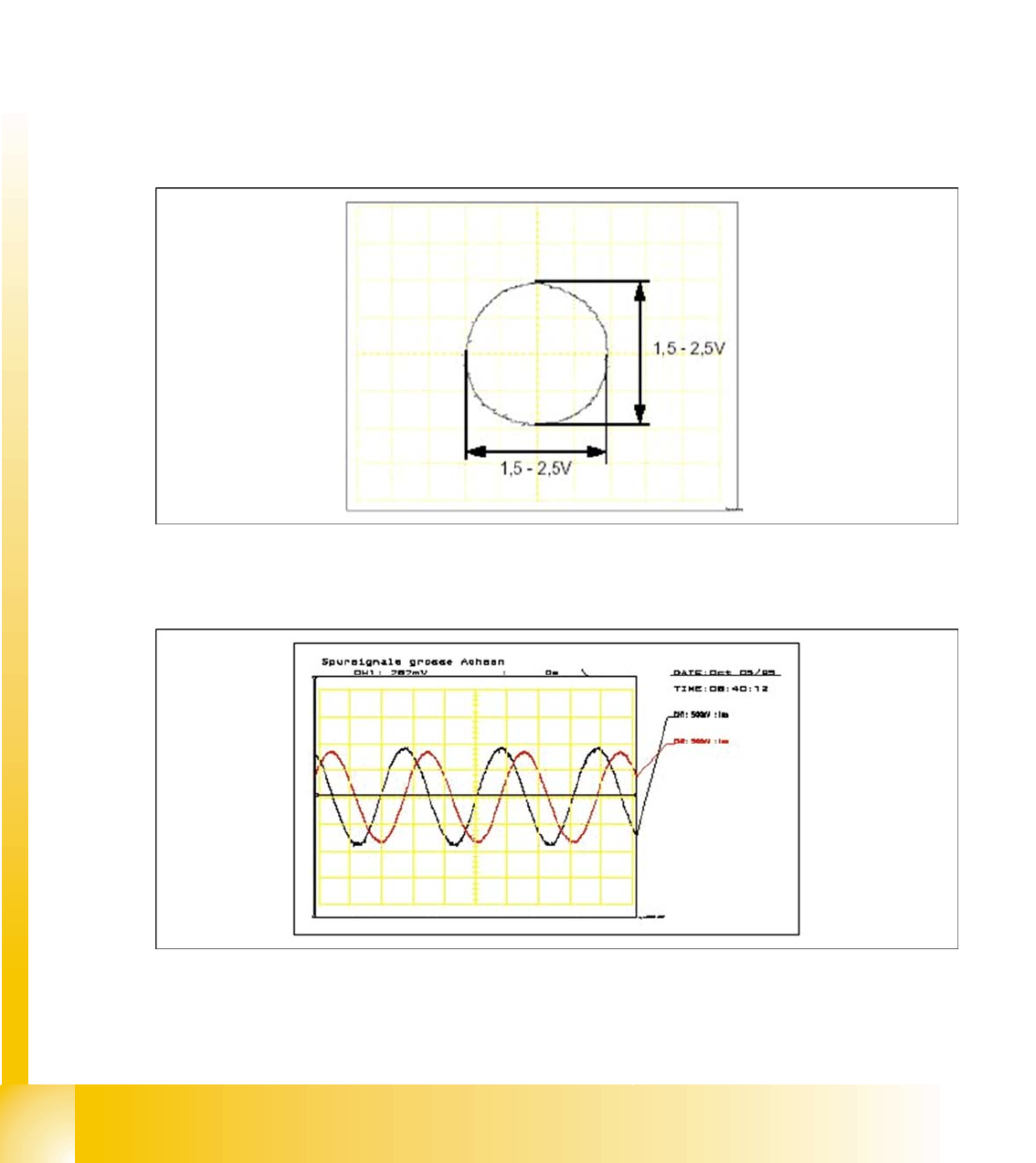
X Move the axis by hand over the whole incremental scale (to check the scale quality).
X The following picture should appear.
7.4 - 3: Analog track signals A and B in X/Y mode
X Switch the oscilloscope to the normal mode.
X The following picture should appear.
7.4 - 4: Analog track signals 90° phase shift
Axis dynamic
Check dynamic X-axis Axis control gantry
Student Guide SIPLACE D4 (FSE)
EN 09/2006 Axis dynamic
155
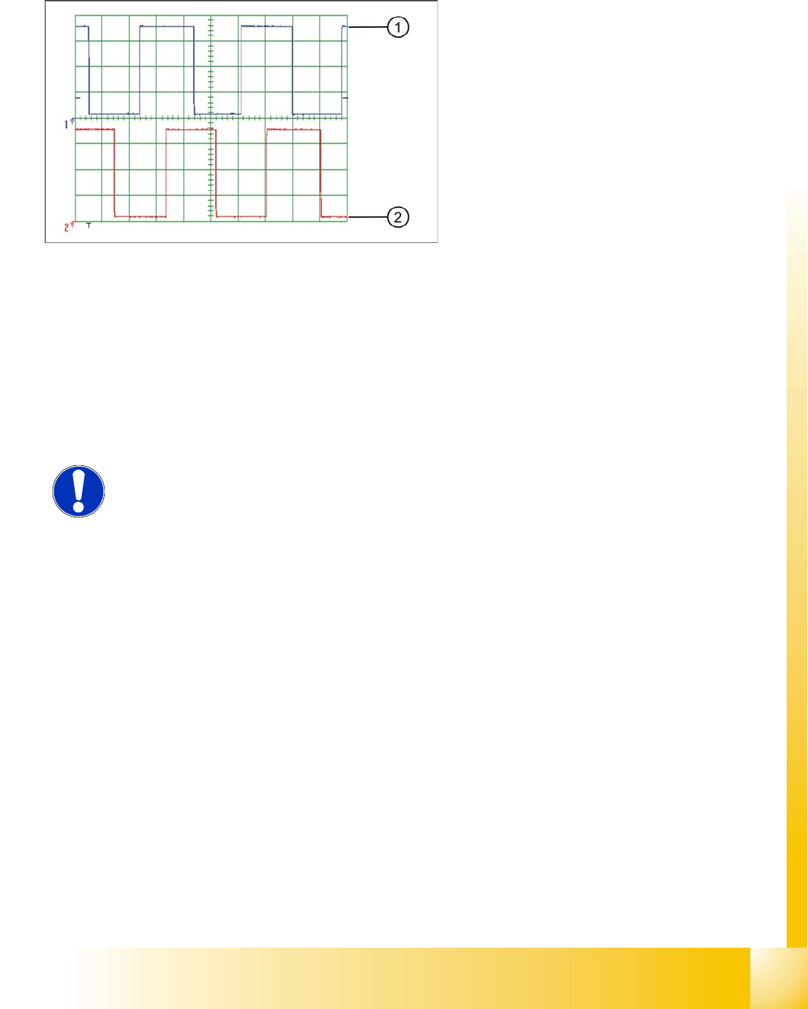
7.4.1.2.4 Digital Track signals
7.4.2 Check dynamic X-axis
The inspection of dynamics occurs with the following signals:
Deviation of position
Uncommutated target current value
Vnom. – speed signal
End signal ( Adapter board Axis in target position)
Actual position = target position signal (upstream end position signal)
Legend:
1. Track A
2. Track B
To check the digital track signals, connect the
track signal tester and the oscilloscope. (see Sec-
tion 7.4.1.1.2 Measuring the Digital Zero Pulse Si-
gnal [J 152]).
The measurement procedure is identical as that
described at Point 7.4.1.2.3 Analog track signals
[J 154] .
NOTE:
For detailed information about checking the dynamics, refer to the settings
instructions.
Before adjusting the axes, ensure that the machine has reached its operating
temperature. Switch the machine on at least 30 minutes before you begin work.