00195193-02 SG D4 FSE en (1).pdf - 第329页
SIPLACE Measurement tools (D4) Student Guide SIPLACE D4 (FSE) EN 09/2006 SIPLACE Meas urement tools (D4) 309 13 SIPLACE Measurement tools (D4) Measurement tools Order No. SIPLACE compressed air tester 00311487-01 Track s…
Sitest
New function in the Sitest program Basic description of all calibration steps
Student Guide SIPLACE D4 (FSE)
EN 09/2006 Sitest
309
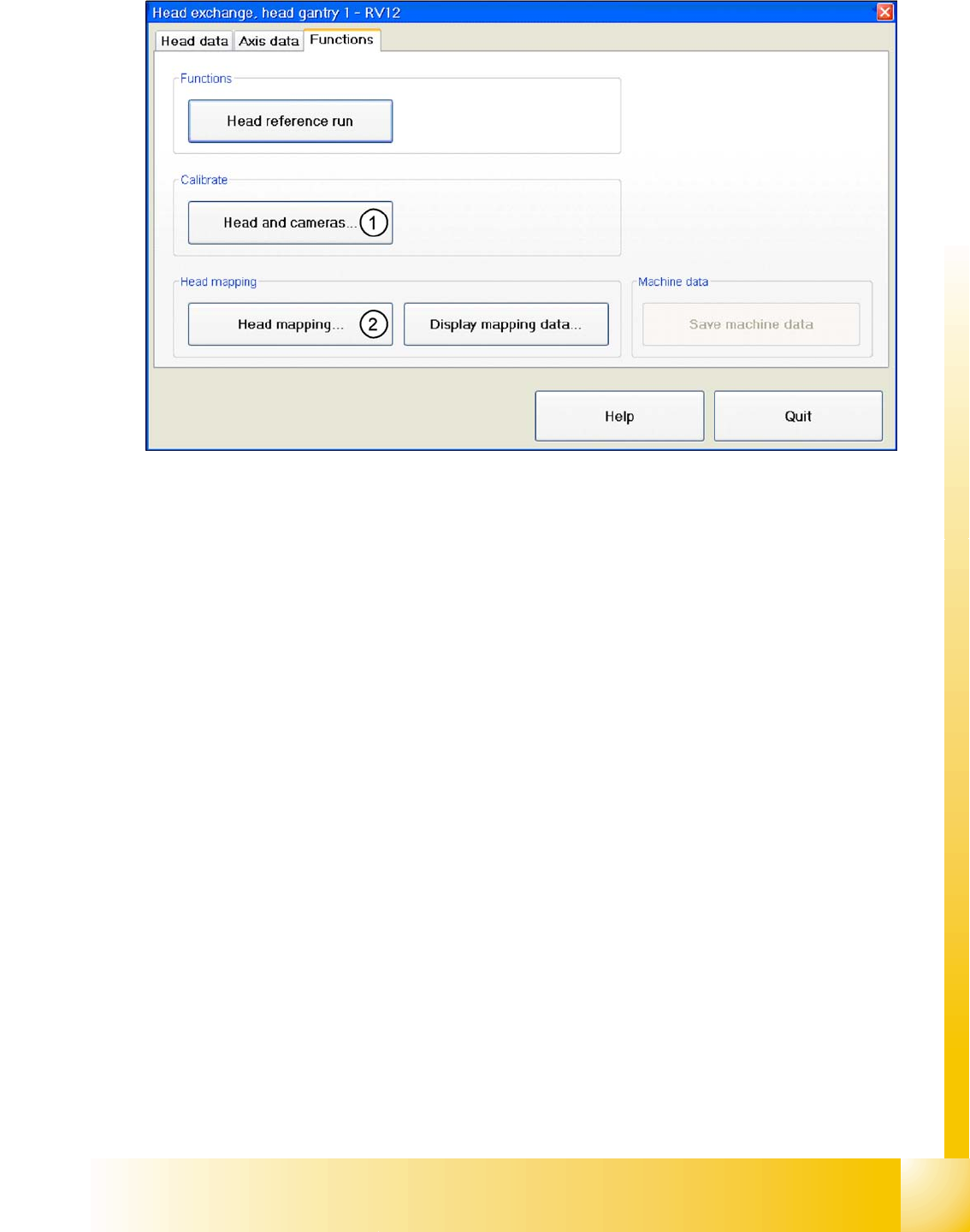
12.3.10.3.3 Functions
12.3 - 11: Head modularity - function
Legend
1. After the head has been replaced, this function enables you to calibrate this head directly in the head
modularity menu. Of course it is also possible to calibrate the other heads with this function. The new
head and other heads can also be calibrated with SITEST, at
Calibrate machine...
,
All heads and
cameras...
.
2. The same applies as in(1). After the head exchange you can directly do a head- mapping. The head
mapping function can be found at
Calibrate machine
,
Head mapping
.
SIPLACE Measurement tools (D4)
Student Guide SIPLACE D4 (FSE)
EN 09/2006 SIPLACE Measurement tools (D4)
309
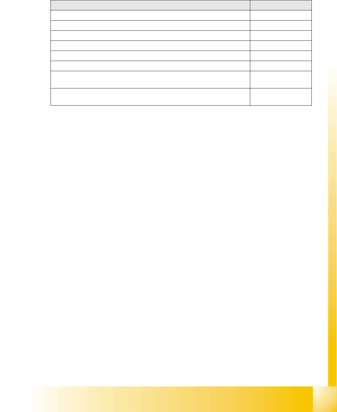
13 SIPLACE Measurement tools (D4)
Measurement tools Order No.
SIPLACE compressed air tester 00311487-01
Track signal tester (from HS50 onwards) 00322510-01
SIPLACE Axis Tester (SAT) 03002801-01
Belt tension tester TSM 00326015-01
Gauge for end position of Z axis for the placement heads C&P6 and C&P12 03019865-01
Set of calibration tools for C&P DLM 00327005-01
calibration tool VISION, Version III
(Vision calibration tool for 505 machines.)
003010565-01
Calibration tool component table
(only for S-tables)
00120040-01
SIPLACE Measurement tools (D4)
SIPLACE AxisTester (SAT) [03002801-xx]
Student Guide SIPLACE D4 (FSE)
SIPLACE Measurement tools (D4) EN 09/2006
310
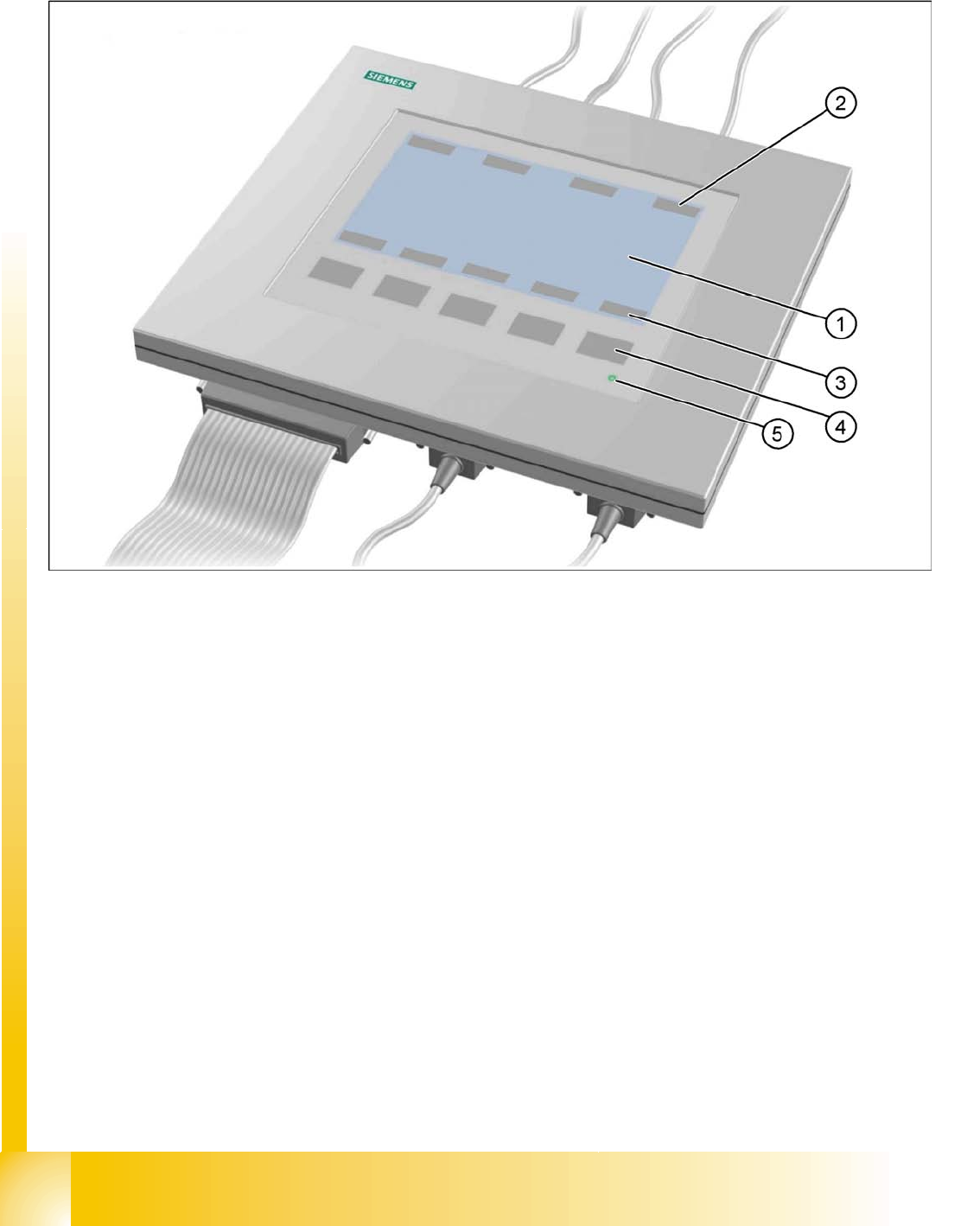
13.1 SIPLACE AxisTester (SAT) [03002801-xx]
13.1 - 1: Axis tester - Frontview
Legend
1. LCD-Display with 240 x 128 pixels, B/W display, with background illumination
The LCD display shows the menus, and graphics of trigger, track and positioning signals.
– time base
– time measurement values
– signal level and
– cursor positions with corresponding time difference values
will be shown alpha numerically on the graphic display.
2. The assignment of the signals to the BNCs is dynamically shown on the LCD display
3. The assignment of the foil keys is dynamically shown on the LCD display
4. Five membrane keys for menu control
5. Green operating display LED