00195193-02 SG D4 FSE en (1).pdf - 第287页
Modular conveyor Light Barrier Functions in Input, Interm ediate and Output Conveyors Conveyor Settings Student Guide SIPLACE D4 (FSE) EN 09/2006 Modular conveyor 271 1 1.3.8 Light Barrier Functi ons in Input, In termedi…
Modular conveyor
Conveyor Settings Function "Constant Transport Time in Placement Area"
Student Guide SIPLACE D4 (FSE)
Modular conveyor EN 09/2006
270
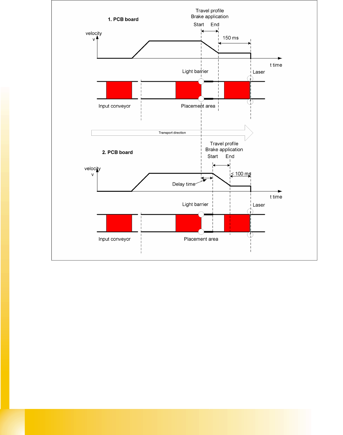
11.3.7 Function "Constant Transport Time in Placement Area"
11.3 - 3: Diagrams PCB braking
The automatic teaching at the beginning of the travel profile guarantees that the stopper is always
reached in the same time, irrespective of the board weight. The transport time remains the same.
Function:
Switching on the laser light barrier
Starting the board braking procedure.
The light barrier in the placement area is used to recognize the board and then start the braking
procedure (travel profile) via the conveyor control software. The software automatically "teaches" the first
board how to move in slow approach mode. Once the travel profile for braking the PCB has begun (on
time), the PCB will be reliably stopped at the laser light barrier, after a maximum of 100ms.
Modular conveyor
Light Barrier Functions in Input, Intermediate and Output Conveyors Conveyor Settings
Student Guide SIPLACE D4 (FSE)
EN 09/2006 Modular conveyor
271
11.3.8 Light Barrier Functions in Input, Intermediate and Output Conveyors
Recognizing and stopping the PCB boards.
Monitoring the boards in the input conveyor i.e.
If a board is recognized in the input conveyor, it will appear on the operating interface and the
machine will lock the conveyor interface to the previous station. When using boards with outbreaks,
the board may stop although the signal of the light barrier is disabled and the interface to the previous
station is opened again. Then the next PCB would move into the input conveyer with the PCB still
lying in the input conveyer. The board monitoring function moves the board backwards and then
transports it forwards again, until the light barrier switches.
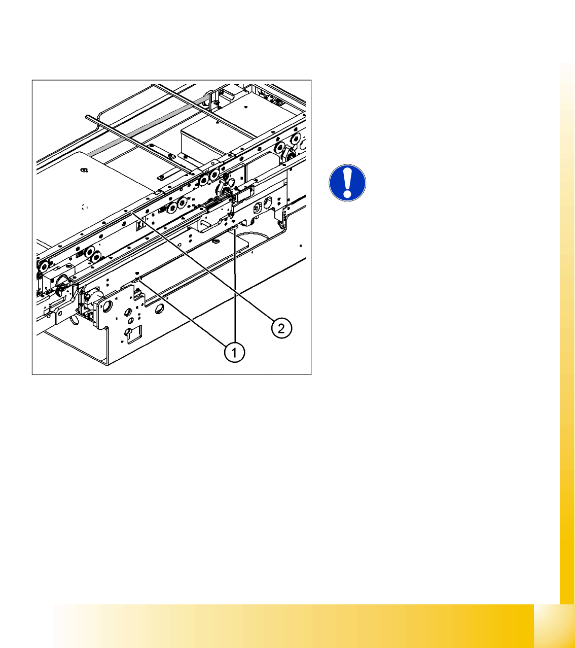
11.3.9 Setting the Clamping Actuator
Legend:
1. Actuator
2. Top edge of conveyor belt
X Set the distance between the actuator and the
top edge of the conveyor belt to 94 mm.
NOTE:
The distance between the clamping
actuator (lifting table) and the top
edge of the belt must be checked at all
four contact points.
Modular conveyor
Conveyor Settings Control of PCB clamping
Student Guide SIPLACE D4 (FSE)
Modular conveyor EN 09/2006
272
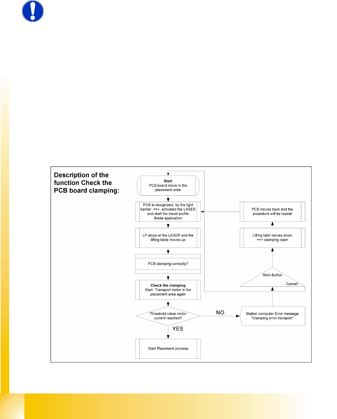
11.3.10 Control of PCB clamping
Function description:
The PCB moves into the placement area, it is recognized by the light barrier, stops at the laser and
the lifting table moves up.
Check PCB clamping: The transport motor in the placement area start again. Is the PCB clamped
correctly the motor current rise up and reach an defined threshold value. Once the board has been
correctly clamped into place, the placement process will begin.
If this threshold is not reached, the system assumes that the board is on its way to the intermediate
or output conveyor and has therefore not been correctly clamped into place.
The station computer will issue the message "PCB not correctly clamped PA1 (PA2)". The process
can be repeated by pressing the "start button".
The lifting table will move downwards, the board will be transported back and the stopper position
will be approached again.
NOTE:
The check whether a PCB is clamping correctly, is controlled with a motor
current check of the transport motor if the PCB board is clamped (Lifting table
up). To check the function you could put a distance plate under the conveyor
side, so that the lifting table can not move to the upper position.
The check is not performed if the option "Vacuum Tooling" is installed.