00195193-02 SG D4 FSE en (1).pdf - 第142页
Services to the machine Various Signals Power Supply Unit Student Guide SIPLACE D4 (FSE) EN 09/2006 Services to the machine 135 6.2.16 V arious Signals 6.2.16.1 Software Releas e (Sof tware Enabled) 6.2 - 12: Software re…

Services to the machine
Power Supply Unit Protective Combination Device (Relay K1)
Student Guide SIPLACE D4 (FSE)
Services to the machine EN 09/2006
134
6.2.15.1 Via PCC K1
The protective contactor combination (PCC) K1 is used as a standard combined protective device. Its
complex configuration, consisting of 3 relays, guarantees maximum protection and operation safety.
The contactor status is shown by LEDs (Power, Channel 1 and Channel 2).
The PCC can be operated via 1 or 2 channels (safety loops).
The D4 only uses one channel, while the other channel is bridged (terminal clamps Y21 and Y22). This
means that the LEDs for both channels shine when the PCC is switched on.
The protective contactor combination K1 switches the contacts 13 and 14, 23 and 24, 33 and 34, plus
the relays SZ2, SZ3 and SZ23.
When this has been completed, K1 is understood to be in the status
24 V supply ON
and the 3 LEDs
Power, Channel 1 and Channel 2 will shine.
6.2.15.2 How is the PCC K1 Enabled?
Precondition:
X The machine must be switched on. Voltage is then present at main contactor SZ1, which is supplied
with 34 V by the transformer and rectifier V7. After SZ1 has contacted, full voltage is present at
transformer T1.
The 24 V voltage supply is now active via fuse F13 and supplies PCC A1 with 24 V. Contactors 13
and 23 of the PCC are switched with relay SZ4.
X The safety loop must be closed, so that 24 V is present at contacts Y10, 11 and 12. That means, the
protective covers, the emergency stop button, the component tables and the feeder cover flaps all
need to be connected/closed.
X The ready signal informs the software that the PCC has triggered and that everything is OK.
6.2.15.3 Pressing the Start Button
Pressing the start button triggers the following actions:
The start signal pulse enables relay 1 and closes contacts 13 and 14.
The 24 V software release signal is sent via the I/O assembly output to relay SZ4, which then closes
contacts 5 and 6.
Contacts 13 and 14, 23 and 24, 33 and 34 of the PCC are now closed.
The
St_XY
signal is sent via contact 14 of the PCC to the inrush current limiter input. Relay 1 is
enabled via NTC thermistors. The relay 1 contacts simultaneously switch the ground A2 (-) of relays
SZ2 and SZ3. Voltage U/V/W_XY is now transmitted via the inrush current resistors until relay 2 of
the inrush current limiter is enabled.
Relay 2 switches SZ23 and full voltage is then present at the X and Y servos.
The voltage flows directly via the relays.
Services to the machine
Various Signals Power Supply Unit
Student Guide SIPLACE D4 (FSE)
EN 09/2006 Services to the machine
135
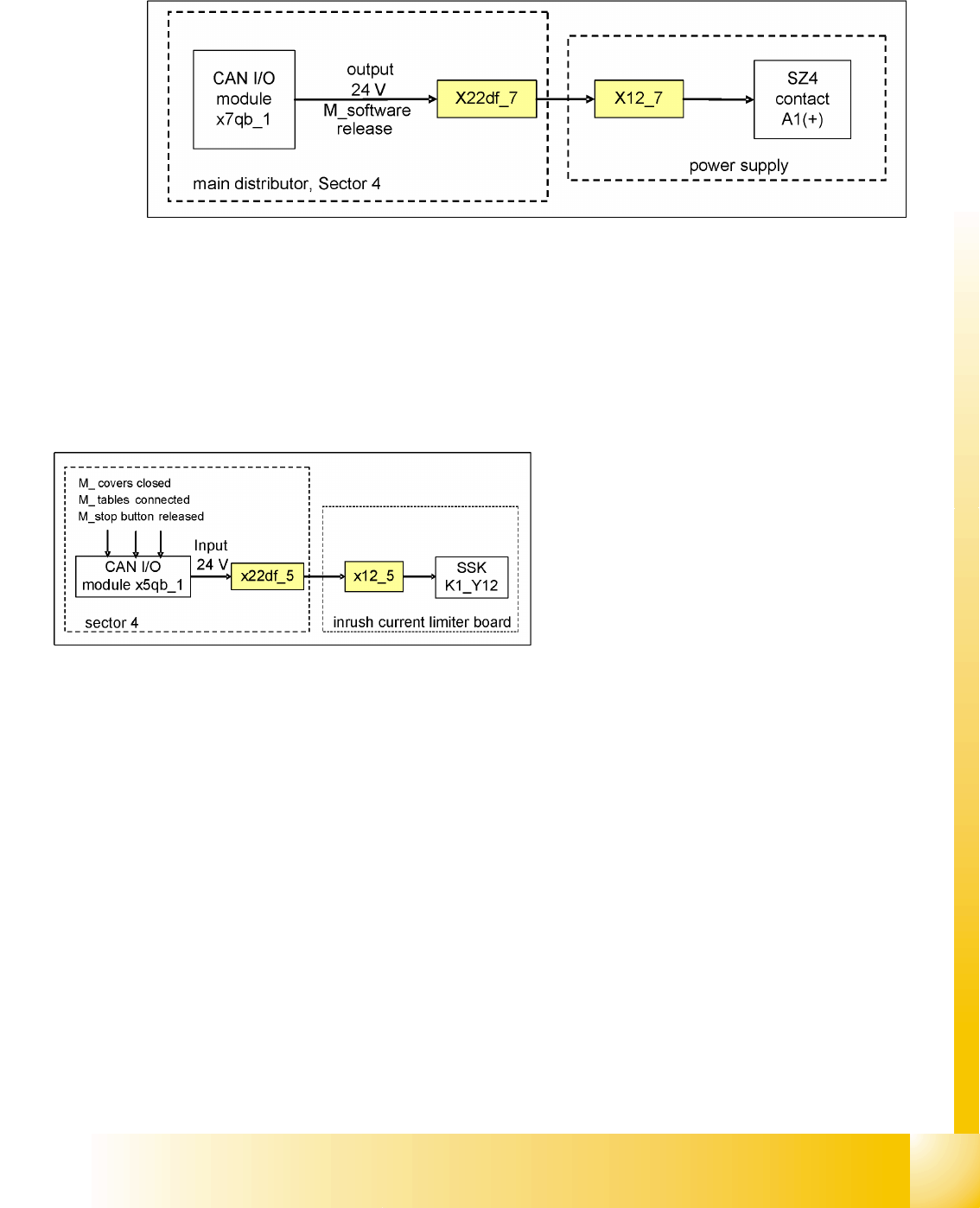
6.2.16 Various Signals
6.2.16.1 Software Release (Software Enabled)
6.2 - 12: Software release signal
The software release signal is emitted by the CAN I/O card, as soon as the MC has finished booting and
the start button has been pressed. Communication also needs to be established to the Vision system,
the axis controllers, the CAN bus and the stations/line computers (except in stand-alone mode). Once
the start button is pressed, the 24 V output signal is sent via the CAN I/O module to SZ24, contact A1.
If the emergency stop circuit is broken, the software release will not be given.
6.2.16.2 Safety Loop OK signal
The message
Safety loop OK
will be emitted by
the CAN I/O module, if the following conditions
have been fulfilled:
All covers closed
All component tables connected
All emergency stop buttons released
The emergency stop circuit is closed

Services to the machine
Pneumatic System Vacuum Generation at C&P Heads - General Information
Student Guide SIPLACE D4 (FSE)
Services to the machine EN 09/2006
136
6.3 Pneumatic System
6.3.1 Vacuum Generation at C&P Heads - General Information
The air is supplied to the vacuum generator, which produces a vacuum using the venturi principle.
The venturi block actually consists of 2 separate venturi nozzles which produce vacuum for 2 circuits,
the holding circuit and the pick up / placement circuit.
The level of vacuum produced is dependent on a number of factors. The greatest influence on vacuum
generation is from the Venturi unit. Any leakage from or blockage within the system will result in working
inefficiently and therefore a reduction in the vacuum levels created. The Venturi unit must be absolutely
airtight and the nozzles in very good condition and of high quality.
One factor which can impair vacuum generation is the altitude. The higher above sea level a machine is
located, the low the ambient pressure will be in the room surrounding it. Therefore at high altitude low
vacuum levels are created, A SIPLACE machine in Munich, at an altitude of 500 m above sea level, can
generate a closed vacuum of approx. 870 mbar, while a machine at sea level in England would be able
to produce approx. 920 mbar.
Another factor influencing the vacuum values is the weather. Stormy, rainy days occur in periods of low
pressure. Vacuum generation during this weather may produce 880 mbar, while the same procedure a
week later, on a sunny day in a high pressure period, could well produce closed vacuum results of 900
mbar.
These 2 cases are only examples and no specific case / figures are used, but this just illustrateswhat
can happen. In any case, it is important that you use an efficient, high quality vacuum system.
The vacuum measurement board is located directly above the vacuum generator and measures the
vacuum values in the hold and pickup/placement circuits. Small tubes are attached to the back of the
Collect & Place head that measure the circuit pressures at the vacuum distributor. These tubes are
connected to pressure sensors. The analogue outputs of these sensors are supplied to A/D converters.
The resulting signals are then sent via the CAN-Bus to the machine controller.