00195193-02 SG D4 FSE en (1).pdf - 第221页
C&P12 Placement Head Placement Procedure Optical Nozzle Query S tudent Guide SIPLACE D4 (FSE) C&P12 Placement Head EN 09/2006 206 9.2.25 Optical Nozzle Query 1. After placement of the fir st board, the nozzle req…
C&P12 Placement Head
Positioning into Placement Angle Placement Procedure
Student Guide SIPLACE D4 (FSE)
EN 09/2006 C&P12 Placement Head
205
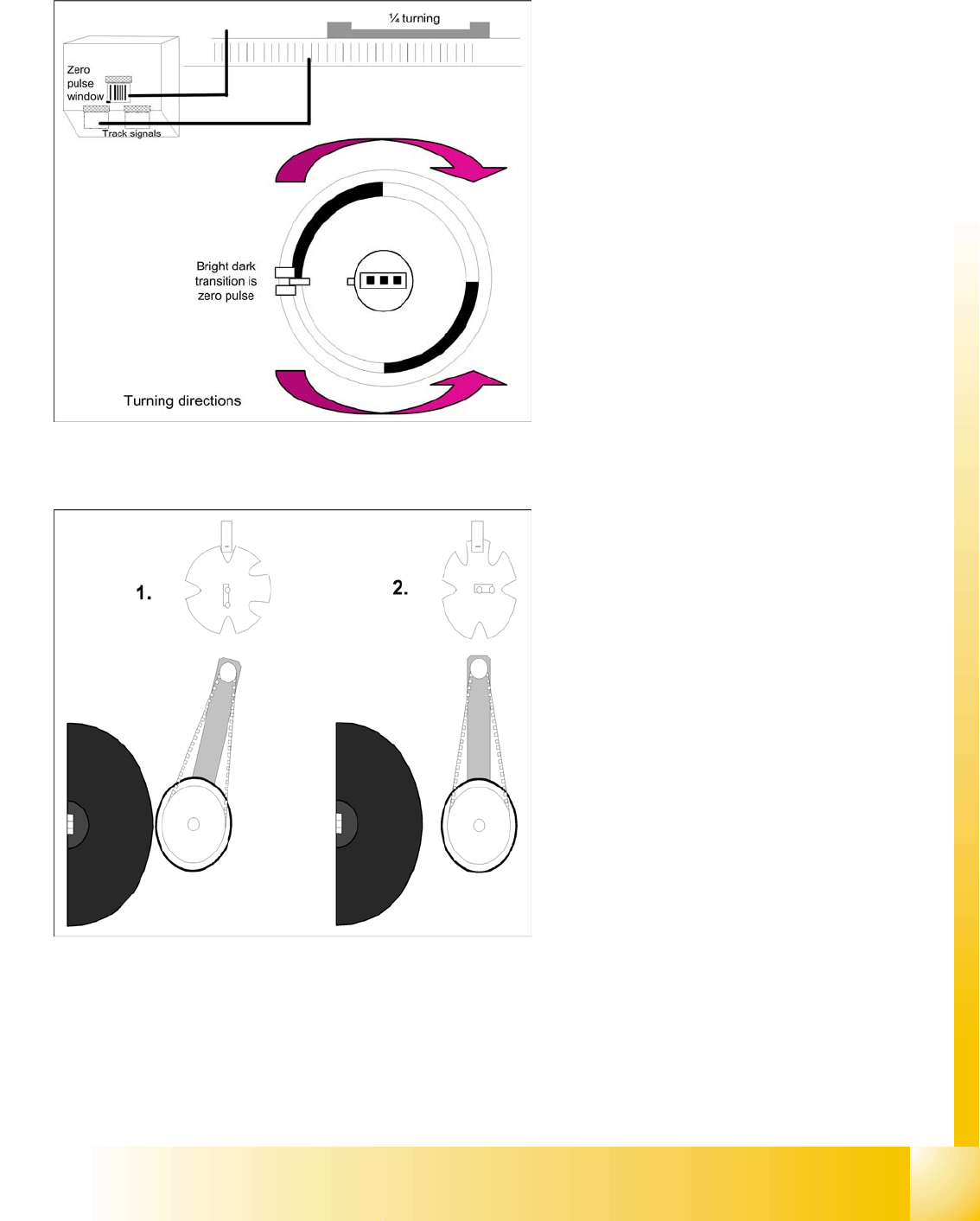
9.2.23 Positioning into Placement Angle
9.2.24 Detailed rotation of DP station, 3. Swivel Out
When positioning begins, the actual position of
the axis is set to 0 by setting the position
counter of the DP axis to 0.
The DP drive is operated in relative positioning
mode.
The DP axis starts to move towards the target
position which is calculated from the station
calibration values, the line computer
programming values and the centering values
of the placement procedure.
An end position signal is emitted as soon as
the actual position deviation is within the
permitted tolerance.
The command to start swiveling out is the end
position signal from DP positioning.
The DP drive is still located at the sleeve.
Diagram 1 shows the status when swiveled in.
The stepping motor is controlled by the light
barrier on the cam disk.
From its swiveled-in status, the stepping motor
rotates by 90° in a counterclockwise direction,
to swivel out.
Diagram 2 shows the status when swiveled
out.

C&P12 Placement Head
Placement Procedure Optical Nozzle Query
Student Guide SIPLACE D4 (FSE)
C&P12 Placement Head EN 09/2006
206
9.2.25 Optical Nozzle Query
1. After placement of the first board, the nozzle request is enabled:
– All nozzles listed for optical checking will be measured by the CO camera (nozzles such as 901,
904, 911, 914, 925).
– From SW 601, these can be found in the nozzle.lib.xml
– If measurement detects a light point of a defined size and brightness, the machine will issue the
message "nozzle worn down or contaminated".
2. Due to the low component height, small nozzles may touch the soldering paste or adhesive if a
component has slipped.
3. The number of components per segment (number of head cycles), after the next nozzle query has
been performed, should be adjusted to the customer's process requirements. This test is always
performed after board processing has been completed.
4. Another option can also be set:
– Nozzle scanning is not a fatal error and although the machine will show the error, it will not stop.
9.2.26 Air Kiss Control During Placement
This function takes a programming option which was designed for the TWIN and uses it as follows for
the C&P placement head.
Air kiss control during placement
Entering "0" means that the air kiss valve will not be switched on.
(1) Entering "1-50" means that the air kiss valve will be switched off when the stepping motor starts.
(2) Entering "51-150" means that the air kiss valve will be switched off when the stepping motor
rotates by 90°.
(3) Entering "151-255" means that the air kiss valve will be switched off when the light barrier is up
or when the stepping motor rotates by 180°.
No entry "----" (the conversion 501/502 to 503 means switching procedure as in (3) (standard).
Air kiss control for place back (do not reject)
(4) Entry and description as in (1)
(5) Entry and description as in (2)
(6) Entering "151-255" means that the air kiss valve will be switched off when the stepping motor
rotates by 180°.
C&P12 Placement Head
Z-Axis Down Travel Profile - Pickup
Student Guide SIPLACE D4 (FSE)
EN 09/2006 C&P12 Placement Head
207
9.3 Travel Profile - Pickup
9.3.1 Z-Axis Down
9.3.1.1 Detailed Standard Pickup Procedure: Z-Axis Down
Start gantry axes to pickup position of next feeder
and communication with CO table: Start signal to
gantry axes
Start signal X & Y axis to next feeder/this
opens the feeder flap
End position signal for X/Y and star axes:
End position signal for star axis
Enables vacuum query: "segment airtight?"
before pickup
X/Y end position signals available.
Z-axis starts:
Z-axis starts positioning downwards
Light barrier (LB) up switches:
Release signal for function LB down after a
waiting period of approx. 3.6 ms
LB down switches:
End position signal for positioning Z-axis down
and valve positioning drive ON for vacuum.