00195193-02 SG D4 FSE en (1).pdf - 第123页
Services to the machine Power Supply Unit S tudent Guide SIPLACE D4 (FSE) Services to t he machine EN 09/2006 11 6 6.2 Power Supply Unit The main power suppl y unit is mounted on a compact s lide-in module, and located o…
Services to the machine
Overview
Student Guide SIPLACE D4 (FSE)
EN 09/2006 Services to the machine
115
6 Services to the machine
6.1 Overview
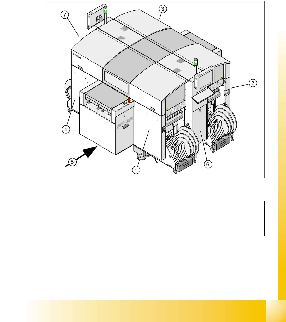
The diagram below shows where the energy supplying and distributing components for system operation
are installed:
6.1 - 1: Main components in SIPLACE D4
Legend:
1 Sector distributor for sector 1 5 Transport direction
2 Sector distributor for sector 2 6 Pneumatic unit
3 Sector distributor for sector 3 7 Power Supply Unit
4 Sector distributor for sector 4
Services to the machine
Power Supply Unit
Student Guide SIPLACE D4 (FSE)
Services to the machine EN 09/2006
116
6.2 Power Supply Unit
The main power supply unit is mounted on a compact slide-in module, and located on the left side of the
middle section. When viewed from the outside only the red main power switch is visible.
A lockable door prevents access to the power supply.
With the open cover, the state of the following protective devices can be quite easily monitored.
Motor protection switch
main contactor
Safety relay
Power circuit breaker
The following work must be performed to adjust the power supply to the country-specific requirements
(see also the conversion instructions for 3x 208 V to 3x 400 V and vice versa):
X Rewiring line supply cable/transformer
X Motor protecting switch
X Inrush current limiter connections
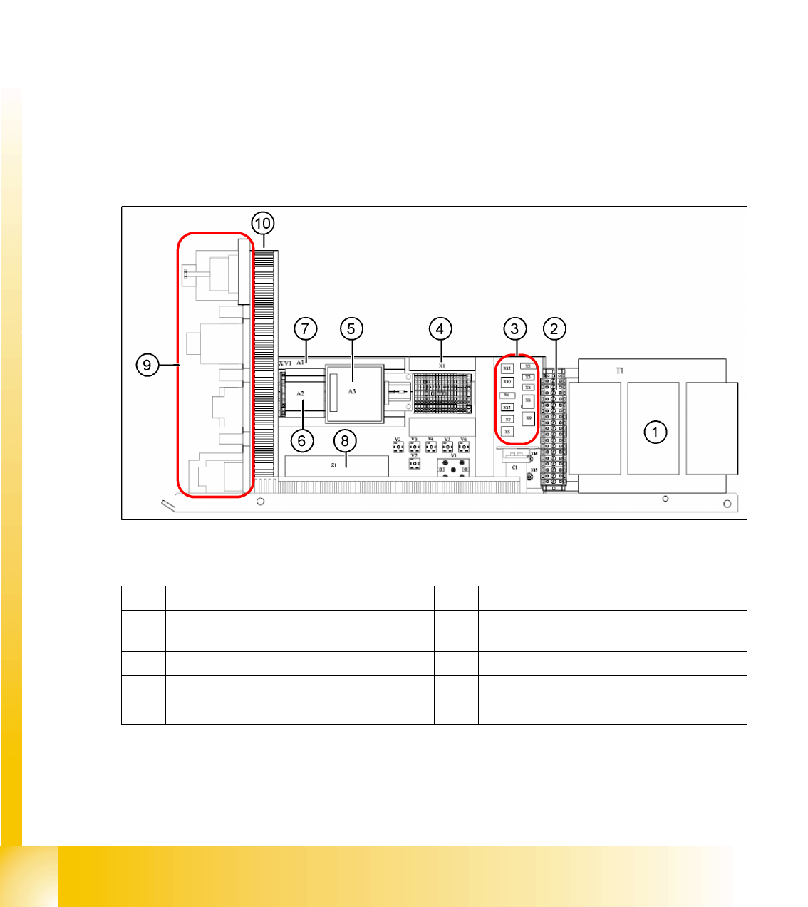
6.2 - 1: Main power supply - side view
Legend
1 Transformer 1 6 Power supply A2 (5 V/6.3 A)
2 Secondary terminal strip with fuses (output
voltage T1)
7 Power supply A1 (24 V/40 A)
3 Connector strip X2-X10, X12, X13 8 Line filter Z1 (input voltage)
4 Terminal strip X1 9 Front view (see following diagram)
5 Power fail board A3 10 Inrush current limiter (behind the cable duct)
Services to the machine
Power Supply Unit
Student Guide SIPLACE D4 (FSE)
EN 09/2006 Services to the machine
117
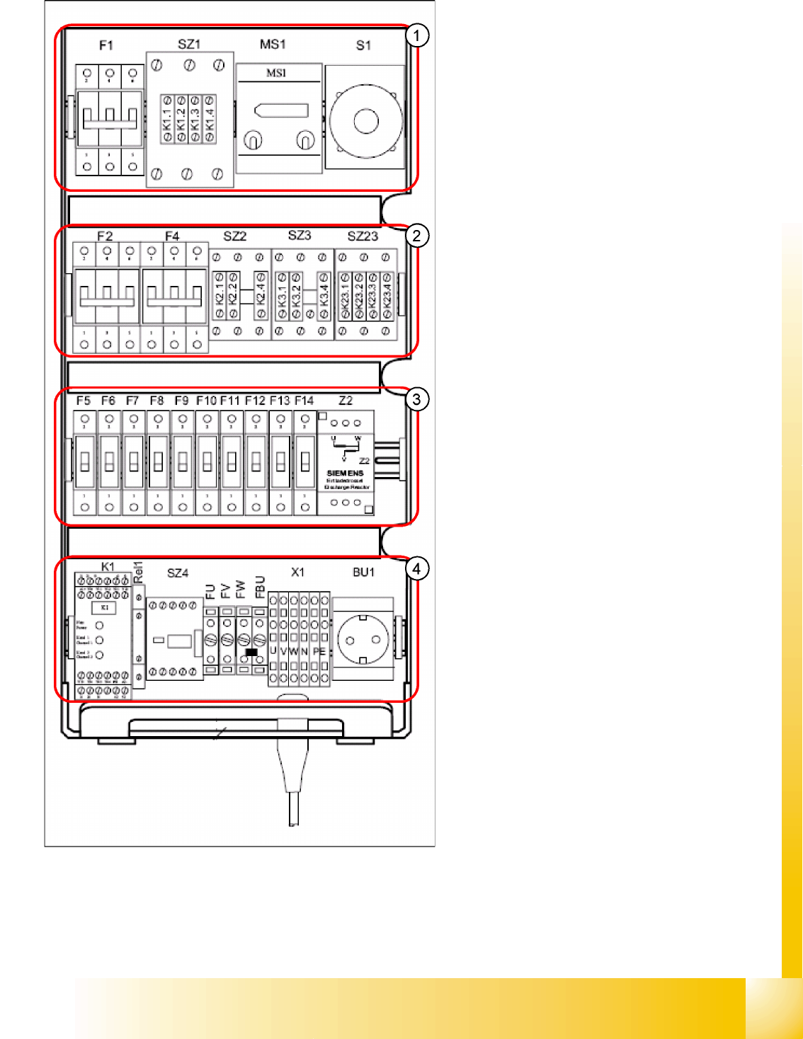
Legend:
1. F1: 3x 230 V AC
SZ1: main contactor
MS1: Motor protection switch
S1: main switch
2. F2: 220 V AC for 5 V power supply
F4: 3x 140 VAC X/Y axes
SZ2,SZ3, SZ23: auxiliary contactors U,V,W for
X/Y servos
3. F5: 150 V DC star axis servo
F6: 40 V DC Z/DP axis servo
F7: 40 V DC CO table
F8: 40 V DC PCB handling (conveyor)
F9: 8 V DC CO table
F10: 48 V DC Vision illumination
F11: 24 V DC terminal strip distributor 2/4
F12: 24 V DC Microbox PC (MC)/control "ON"
(K1)
F13: 24 V DC Box PC (SR)/axis unit 1/2
F14: 24 V DC conveyor control (CC 301)/
monitors
Z2: discharge inductor
4. K1: protective contactor combination
Relay1: control ON - button
SZ4: control ON - software
FU: fuse 6.3 AT 220 VAC to GND
FV: fuse 6.3 AT 220 VAC to GND
FW: fuse 6.3 AT 220 VAC to GND
FBU: fuse 6.3 AT 220 VAC to GND
X1: feed in - terminal strip
BU1: service socket