00195193-02 SG D4 FSE en (1).pdf - 第261页
Component handling Pneumatic tape cutter Jumper setting on the control unit at the tape cutt er S tudent Guide SIPLACE D4 (FSE) Component handling EN 09/2006 246 10.3.2.2 Pneumatic scheme T ape cutter 10.3.3 Jumper setti…
Component handling
Structure and function of the pneumatic tape cutter Pneumatic tape cutter
Student Guide SIPLACE D4 (FSE)
EN 09/2006 Component handling
245
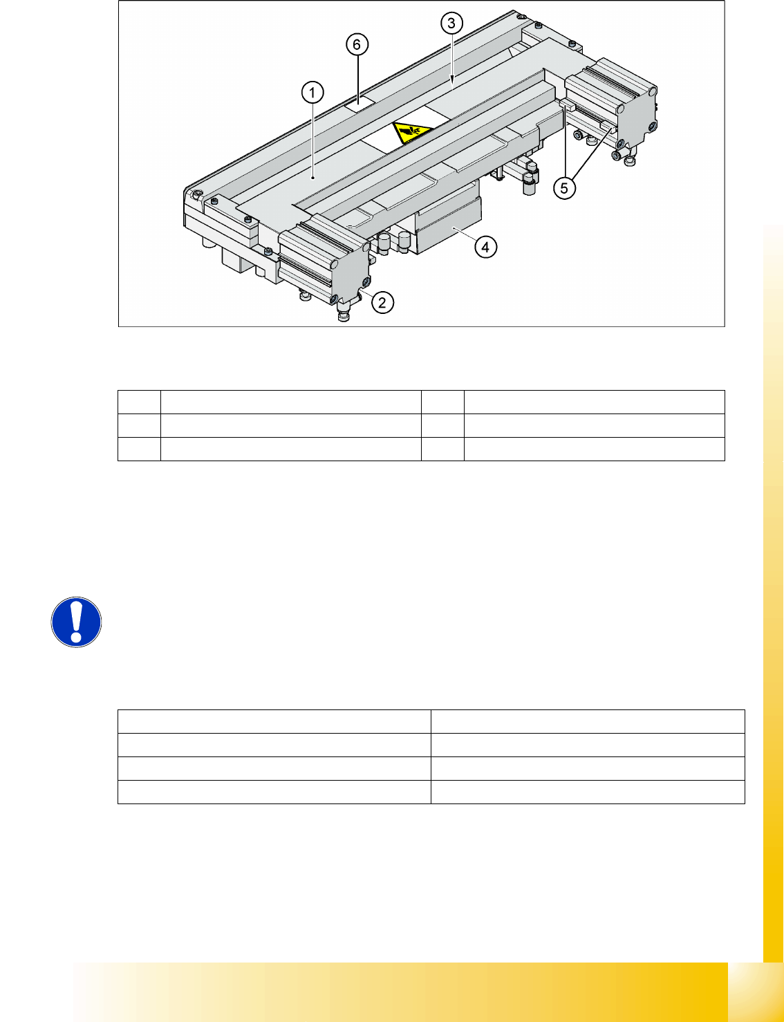
10.3 - 1: Pneumatic tape cutter
Legend
The tape cutter is activated when the gantry is moving to the placement position. Alternating one of the
cylinders start to front position. Once the first cylinder reaches the front position, the second cylinder is
started. Both signals ’blade in front position’ trigger control unit to withdraw both cylinders at the same
time.
10.3.2.1 Technical data
1 Horizontal frame 4 Electronic control unit
2 Pneumatic cylinder 5 Proximity switch
3 Slot for empty tape 6 Fixed blade
NOTE:
The cutter can be removed within about 15 minutes for service purposes. For
detailed information about dismantling, refer to the service manual.
Compressed air supply 0.5 MPa = 5.0 bar
Compressed air consumption 135 l/min.
Cycle time 1.5 sec per cut
Supply voltages 5 VDC, 24 VDC
Component handling
Pneumatic tape cutter Jumper setting on the control unit at the tape cutter
Student Guide SIPLACE D4 (FSE)
Component handling EN 09/2006
246
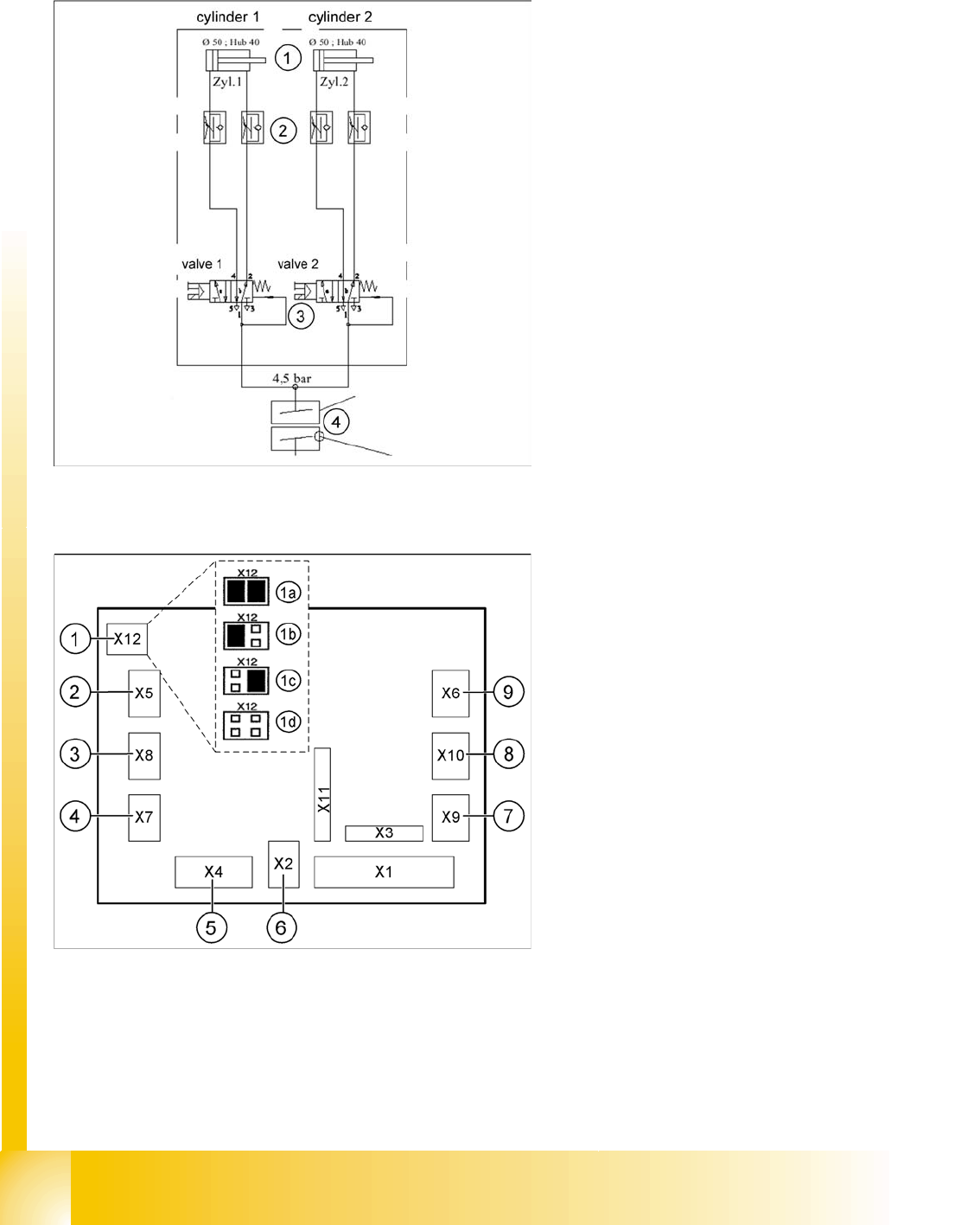
10.3.2.2 Pneumatic scheme Tape cutter
10.3.3 Jumper setting on the control unit at the tape cutter
The jumper for the CAN bus addressing must be set according to the corresponding location in the
machine.
Legend:
1. Drive cylinder for cutter blade movement
40 mm stroke
2. Adjustable throttle valve on the pneumatic
cylinder
3. 5/2 way magnetic valve
4. 4.5 bar compressed air supply and 24 V
voltage supply via the PCC safety relay
Cutter only active when protective hoods are
closed
Legend - SIPLACE D4 Jumpers
1. X12 – Jumper for location code of cutter:
1a: Gantry 1
1b: Gantry 2
1c: Gantry 3
1d: Gantry 4
2. X5 – Voltage supply to valve (left)
3. X8 – Proximity switch for stroke cylinder out
(left)
4. X7 – Proximity switch for stroke cylinder in
(left)
5. X4 – CAN bus connection
6. X2 – Voltage supply for cutter +24 V and +5 V
7. X9 – Proximity switch for stroke cylinder in
(left)
8. X10 – Proximity switch for stroke cylinder out
(right)
9. X6 – Voltage supply to valve (right)
Component handling
Empty tape duct Pneumatic tape cutter
Student Guide SIPLACE D4 (FSE)
EN 09/2006 Component handling
247
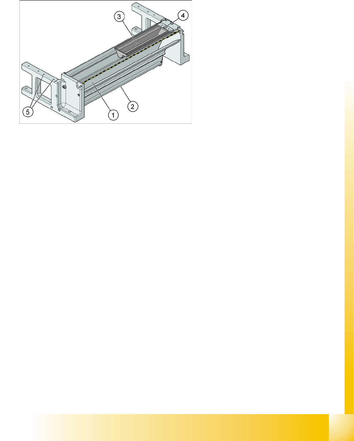
10.3.4 Empty tape duct
The empty tape duct receives empty tapes from the feeders at the inlet gap (1) and guides these to the
outlet gap (2), to the cutting position of the pneumatic cutter. This is where the tape is cut up and falls
down the waste tape chute, into the CO trolley waste tape container.
The empty tape duct is fixed to the pneumatic tape cutter with four screws.
The empty tape duct acts as a base for further modules:
The removable nozzle reject container (3)
Installation surface(5) for C&P nozzle changer
Nozzle stripping unit (4)
Legend:
1. Inlet slot for empty tape
2. Outlet slot for the empty tape above the
pneumatic tape cutter
3. Nozzle reject container
4. Nozzle reject station
5. assembly surface for the nozzle changer